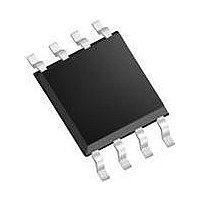
MCP9804-E/MS Microchip Technology, MCP9804-E/MS Datasheet - Page 28

MCP9804-E/MS
Manufacturer Part Number
MCP9804-E/MS
Description
IC TEMP SENSOR I2C 2.7V 8MSOP
Manufacturer
Microchip Technology
Specifications of MCP9804-E/MS
Package / Case
8-MSOP, Micro8™, 8-uMAX, 8-uSOP,
Function
Temp Monitoring System (Sensor)
Topology
ADC (Sigma Delta), Register Bank
Sensor Type
Internal
Sensing Temperature
-40°C ~ 125°C
Output Type
I²C™/SMBus™
Output Alarm
No
Output Fan
No
Voltage - Supply
2.7 V ~ 5.5 V
Operating Temperature
-40°C ~ 125°C
Mounting Type
Surface Mount
Temperature Threshold
+ 150 C
Full Temp Accuracy
+/- 0.25 %
Digital Output - Bus Interface
2-Wire, I2C
Supply Voltage (max)
5.5 V
Supply Voltage (min)
2.7 V
Maximum Operating Temperature
+ 125 C
Minimum Operating Temperature
- 40 C
Supply Current
200 uA
Ic Output Type
Digital
Sensing Accuracy Range
± 0.25°C
Temperature Sensing Range
-40°C To +125°C
Supply Voltage Range
2.7V To 5.5V
Sensor Case Style
MSOP
No. Of Pins
8
Rohs Compliant
Yes
Supply Voltage Min
2.7V
Leaded Process Compatible
Yes
Lead Free Status / RoHS Status
Lead free / RoHS Compliant
Lead Free Status / RoHS Status
Lead free / RoHS Compliant, Lead free / RoHS Compliant
Available stocks
Company
Part Number
Manufacturer
Quantity
Price
Company:
Part Number:
MCP9804-E/MS
Manufacturer:
MICROCHIP
Quantity:
12 000
Part Number:
MCP9804-E/MS
Manufacturer:
MICROCHI
Quantity:
20 000
MCP9804
5.1.5
The upper byte of this register is used to specify the
device identification and the lower byte is used to
specify device revision. The device ID for the MCP9804
is 0x02 (hex).
The revision begins with 0x00 (hex) for the first release,
with the number being incremented as revised versions
are released.
REGISTER 5-6:
FIGURE 5-8:
DS22203B-page 28
bit 15
bit 7
Legend:
R = Readable bit
-n = Value at POR
bit 15-8
bit 7-0
SDA
SCL
R-0
R-0
SDA
SCL
DEVICE ID AND REVISION
REGISTER
S
Device ID: Bit 15 to bit 8 are used for device ID
Device Revision: Bit 7 to bit 0 are used for device revision
1
0
S
2
0
1
0
R-0
R-0
DEVICE ID AND DEVICE REVISION (READ-ONLY) → ADDRESS
Address Byte
Timing Diagram for
3
1
2
0
Address Byte
4
1
3
1
A
5
2
4
1
W = Writable bit
‘1’ = Bit is set
6
A
1
A
5
2
R-0
R-0
A
7
0
6
A
1
MCP9804
W
8
A
7
0
MCP9804
A
C
K
8
R
Reading Device ID and Device Revision Register
1
0
A
C
K
2
Device ID Pointer
R-0
R-0
0
1
0
Device Revision
3
0
2
0
Device ID
4
0
3
0
MSB Data
U = Unimplemented bit, read as ‘0’
‘0’ = Bit is cleared
5
0
4
0
6
1
0
5
R-0
R-0
7
1
6
0
MCP9804
8
1
7
1
A
C
K
8
0
Master
A
C
K
R-0
R-0
1
0
Note:
2
0
3
0
LSB Data
© 2009 Microchip Technology Inc.
x = Bit is unknown
4
0
It is not necessary to
select
pointer if it was set from
the previous read/write.
5
0
R-1
R-0
(See Section 4.0).
6
0
‘0000 0111’b
7
0
the
8
0
Master
N
A
K
register
R-0
R-0
P
bit 8
bit 0


