ADT7490ARQZ-REEL ON Semiconductor, ADT7490ARQZ-REEL Datasheet - Page 57
ADT7490ARQZ-REEL
Manufacturer Part Number
ADT7490ARQZ-REEL
Description
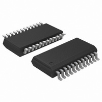
IC THERM MON FAN CTRLR 24-QSOP
Manufacturer
ON Semiconductor
Series
dBCool®r
Datasheet
1.ADT7490ARQZ-R7.pdf
(75 pages)
Specifications of ADT7490ARQZ-REEL
Function
Fan Control, Temp Monitor
Topology
ADC, Comparator, Fan Speed Counter, Multiplexer, Register Bank
Sensor Type
External & Internal
Sensing Temperature
-40°C ~ 125°C, External Sensor
Output Type
SMBus™
Output Alarm
No
Output Fan
Yes
Voltage - Supply
3 V ~ 3.6 V
Operating Temperature
-40°C ~ 125°C
Mounting Type
Surface Mount
Package / Case
24-QSOP
Full Temp Accuracy
14 %
Supply Voltage (max)
3.6 V
Supply Voltage (min)
3 V
Description/function
Remote Thermal Controller
Supply Current
1.5 mA
Lead Free Status / RoHS Status
Lead free / RoHS Compliant
Available stocks
Company
Part Number
Manufacturer
Quantity
Price

Part Number:
ADT7490ARQZ-REEL
Manufacturer:
ANALOGDEVICES
Quantity:
20 000


Table 47. Register 0x5C, Register 0x5D, and Register 0x5E — PWM1, PWM2, and PWM3 Configuration Registers
(Power−On Default = 0x62)
1. This register becomes read-only when the Configuration Register 1 (0x40) LOCK bit is set to 1. Any subsequent attempts to write to this
2. When REPLACE mode is selected, (Register 0x36, Bit 4 set to 1) PWM1 is automatically configured for the alternative behavior setting.
Table 48. Temperature T
1. These registers become read-only when the Configuration Register 1 (0x40) LOCK bit is set. Any further attempts to write to these registers
Bit No.
[2:0]
[7:5]
[3]
[4]
Register Address
register fail.
Register 0x36, Bits [7:5] should be set to 000 only.
have no effect.
0x5F
0x60
0x61
Mnemonic
(Note 2)
BHVR
SPIN
ALT
INV
R/W (Note 1)
R/W (Note 1)
RANGE
R/W
R/W
R/W
R/W
R/W
R/W
R/W
/PWM Frequency Registers
Bit Code
Default Behavior Bits
000
001
010
011
100
101
110
111
These bits control the startup timeout for PWMx. The PWM output stays high until two valid
TACH rising edges are seen from the fan. If there is not a valid TACH signal during the fan
TACH measurement directly after the fan startup timeout period, the TACH measurement reads
0xFFFF and Interrupt Status Register 2 reflects the fan fault. If the TACH minimum high and
low bytes contain 0xFFFF or 0x0000, then the Interrupt Status Register 2 bit is not set, even if
the fan has not started.
Use alternative behavior setting options in Bits [7:5] below for PWMx by setting this bit to 1.
Default = 0.
This bit inverts the PWM output. The default is 0, which corresponds to a logic high output for
100% duty cycle. Setting this bit to 1 inverts the PWM output, so a 100% duty cycle
corresponds to a logic low output.
These bits assign each fan to a particular temperature sensor for localized cooling. Setting Bit 3
to Logic 1 in this register chooses whether the default of alternative behavior option is selected.
000 = Remote 1 temperature controls
PWMx (automatic fan control mode).
001 = Local temperature controls PWMx
(automatic fan control mode).
010 = Remote 2 temperature controls
PWMx (automatic fan control mode).
011 = PWMx runs full speed (default).
100 = PWMx disabled.
101 = Fastest speed calculated by local
and Remote 2 temperature controls PWMx.
110 = Fastest speed calculated by all three
temperature channel controls PWMx.
111 = Manual mode. PWM duty cycle
registers (Register 0x30 to Register 0x32)
become writable.
Remote 1 T
Local T
Remote 2 T
RANGE
RANGE
RANGE
/PWM2 frequency.
http://onsemi.com
Description
/PWM1 frequency.
/PWM3 frequency.
57
Description
Startup Time
Alternative Behavior Bits (Note 2)
No startup timeout
100 ms
250 ms (default)
400 ms
667 ms
1 sec
2 sec
4 sec
000 = PECI0 reading controls PWMx
(automatic fan control mode).
001 = PECI1 reading controls PWMx
(automatic fan control mode).
010 = PECI2 reading controls PWMx
(automatic fan control mode).
011 = PECI3 reading controls PWMx
(automatic fan control mode).
100 = Reserved. If selected, fans run at 100%
duty cycle.
101 = Fastest of all four PECI channels. Fastest
speed calculated by all four PECI readings.
110 = Reserved. If selected, fans run at 100%
duty cycle.
111 = Fastest speed calculated by all of the
thermal zones (Local, Remote 1, Remote 2,
and PECI temperatures).
Power−On Default
0xC4
0xC4
0xC4
Related parts for ADT7490ARQZ-REEL
Image
Part Number
Description
Manufacturer
Datasheet
Request
R

Part Number:
Description:
dBCool Remote Thermal Monitor and Fan Controller
Manufacturer:
Analog Devices
Datasheet:

Part Number:
Description:
ON Semiconductor [VOLTAGE REGULATOR]
Manufacturer:
ON Semiconductor
Datasheet:
Part Number:
Description:
357-036-542-201 CARDEDGE 36POS DL .156 BLK LOPRO
Manufacturer:
ON Semiconductor
Datasheet:
Part Number:
Description:
357-036-542-201 CARDEDGE 36POS DL .156 BLK LOPRO
Manufacturer:
ON Semiconductor
Datasheet:
Part Number:
Description:
357-036-542-201 CARDEDGE 36POS DL .156 BLK LOPRO
Manufacturer:
ON Semiconductor
Datasheet:
Part Number:
Description:
357-036-542-201 CARDEDGE 36POS DL .156 BLK LOPRO
Manufacturer:
ON Semiconductor
Datasheet:
Part Number:
Description:
357-036-542-201 CARDEDGE 36POS DL .156 BLK LOPRO
Manufacturer:
ON Semiconductor
Datasheet:
Part Number:
Description:
357-036-542-201 CARDEDGE 36POS DL .156 BLK LOPRO
Manufacturer:
ON Semiconductor
Datasheet:
Part Number:
Description:
357-036-542-201 CARDEDGE 36POS DL .156 BLK LOPRO
Manufacturer:
ON Semiconductor
Datasheet:
Part Number:
Description:
357-036-542-201 CARDEDGE 36POS DL .156 BLK LOPRO
Manufacturer:
ON Semiconductor
Datasheet:
Part Number:
Description:
357-036-542-201 CARDEDGE 36POS DL .156 BLK LOPRO
Manufacturer:
ON Semiconductor
Datasheet:
Part Number:
Description:
357-036-542-201 CARDEDGE 36POS DL .156 BLK LOPRO
Manufacturer:
ON Semiconductor
Datasheet:
Part Number:
Description:
Manufacturer:
ON Semiconductor
Datasheet:
Part Number:
Description:
Manufacturer:
ON Semiconductor
Datasheet: