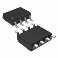
DS1626S+T&R Maxim Integrated Products, DS1626S+T&R Datasheet - Page 9

DS1626S+T&R
Manufacturer Part Number
DS1626S+T&R
Description
IC THERMOMETER/STAT DIG 8-SOIC
Manufacturer
Maxim Integrated Products
Datasheet
1.DS1626U.pdf
(12 pages)
Specifications of DS1626S+T&R
Function
Thermometer, Thermostat
Topology
ADC (Sigma Delta), Comparator, Register Bank
Sensor Type
Internal
Sensing Temperature
-55°C ~ 125°C
Output Type
3-Wire Serial
Output Alarm
Yes
Output Fan
No
Voltage - Supply
2.7 V ~ 5.5 V
Operating Temperature
-55°C ~ 125°C
Mounting Type
Surface Mount
Package / Case
8-SOIC (5.3mm Width), 8-SOP, 8-SOEIAJ
Full Temp Accuracy
+/- 2 C
Digital Output - Bus Interface
Serial (3-Wire)
Digital Output - Number Of Bits
12 bit
Maximum Operating Temperature
+ 125 C
Minimum Operating Temperature
- 55 C
Lead Free Status / RoHS Status
Lead free / RoHS Compliant
CONFIGURATION REGISTER
The configuration register allows the user to customize the DS1626/DS1726 conversion and thermostat
options. It also provides information to the user about conversion status, EEPROM activity, and
thermostat activity. The configuration register is arranged as shown in Figure 6 and detailed descriptions
of each bit are provided in Table 3. This register can be accessed using the Read Config and Write Config
commands. Note that the R1, R0, CPU, and 1SHOT bits are stored in EEPROM and all other
configuration register bits are SRAM.
Figure 6. CONFIGURATION REGISTER
Table 3. CONFIGURATION REGISTER BIT DESCRIPTIONS
*NV (EEPROM)
(USER ACCESS)
(Read/Write)
(Read/Write)
(Read/Write)
(Read/Write)
(Read/Write)
(Read/Write)
BIT NAME
(Read Only)
(Read Only)
1SHOT*
DONE
CPU*
NVB
THF
TLF
R1*
R0*
*NV (EEPROM)
DONE
MSb
Power-up state = 1.
DONE = 0. Temperature conversion is in progress.
DONE = 1. Temperature conversion is complete.
Power-up state = 0.
THF = 1. The measured temperature has reached or exceeded the value stored in the
T
power is cycled, or a Software POR command is issued.
Power-up state = 0.
TLF = 1. The measured temperature has equaled or dropped below the value stored
in the T
power is cycled, or a Software POR command is issued.
Power-up state = 0.
NVB = 1. Write to an E
NVB = 0. NV memory is not busy.
Power-up state = last value written to this bit.
Sets conversion resolution (see Table 4).
Initial state from factory = 1.
Power-up state = last value written to this bit.
Sets conversion resolution (see Table 4).
Initial state from factory = 1.
Power-up state = last value written to this bit.
CPU = 1. Stand-alone mode is disabled.
CPU = 0. Stand-alone mode is enabled when RST = 0. See CPU BIT AND STAND-
ALONE THERMOSTAT OPERATION section for more information.
Initial state from factory = 0.
Power-up state = last value written to this bit.
1SHOT = 1: One-Shot Mode. The Start Convert T command initiates a single
temperature conversion and then the device goes into a low-power standby state.
1SHOT = 0: Continuous Conversion Mode. The Start Convert T command initiates
continuous temperature conversions.
Initial state from factory = 0.
H
BIT 6
THF
register. THF will remain a 1 until it is overwritten with a 0 by the user, the
L
register. TLF will remain a 1 until it is overwritten with a 0 by the user, the
BIT 5
TLF
NVB
2
BIT 4
FUNCTIONAL DESCRIPTION
memory cell is in progress.
9 of 12
BIT 3
R1*
BIT 2
R0*
CPU*
BIT 1
1SHOT*
LSb
DS1626/DS1726


