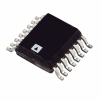
ADT7517ARQ Analog Devices Inc, ADT7517ARQ Datasheet - Page 37

ADT7517ARQ
Manufacturer Part Number
ADT7517ARQ
Description
IC TEMP SNSR QUAD DAC 16-QSOP
Manufacturer
Analog Devices Inc
Datasheet
1.ADT7517ARQZ.pdf
(44 pages)
Specifications of ADT7517ARQ
Rohs Status
RoHS non-compliant
Function
Temp Monitoring System (Sensor)
Topology
ADC, Comparator, Multiplexer, Register Bank
Sensor Type
External & Internal
Sensing Temperature
-40°C ~ 120°C, External Sensor
Output Type
I²C™, MICROWIRE™, QSPI™, SPI™
Output Alarm
No
Output Fan
No
Voltage - Supply
2.7 V ~ 5.5 V
Operating Temperature
-40°C ~ 120°C
Mounting Type
Surface Mount
Package / Case
16-QSOP
Available stocks
Company
Part Number
Manufacturer
Quantity
Price
Company:
Part Number:
ADT7517ARQZ
Manufacturer:
Analog Devices Inc
Quantity:
135
SERIAL INTERFACE
There are two serial interfaces that can be used on this part, I
and SPI. The device powers up with the serial interface in I
mode, but it is not locked into this mode. To stay in I
is recommended that the user tie the CS line to either V
GND. It is not possible to lock the I
select and lock the SPI mode.
To select and lock the interface into the SPI mode, a number of
pulses must be sent down the CS line (Pin 4). The following
section describes how this is done.
Once the SPI communication protocol has been locked in, it
cannot be unlocked while the device is still powered up. Bit D0
of the SPI lock status register (Address 0x7F) is set to 1 when a
successful SPI interface lock has been accomplished. To reset
the serial interface, the user must power down the part and
power it up again. A software reset does not reset the serial
interface.
Serial Interface Selection
The CS line controls the selection between I
Figure 59 shows the selection process necessary to lock the SPI
interface mode.
To communicate to the ADT7516/ADT7517/ADT7519 using
the SPI protocol, send three pulses down the CS line as shown
in Figure 59. On the third rising edge (marked as C in Figure 59),
the part selects and locks the SPI interface. The user is now
limited to communicating to the device using the SPI protocol.
(START HIGH)
(START LOW)
CS
CS
A
A
2
C mode, but it is possible to
Figure 59. Serial Interface—Selecting and Locking SPI Protocol
2
C and SPI.
B
B
2
C mode, it
CC
or
2
C
Rev. B | Page 37 of 44
2
C
THIRD RISING EDGE
THIRD RISING EDGE
SPI LOCKED ON
SPI LOCKED ON
C
C
As per most SPI standards, the CS line must be low during
every SPI communication to the ADT7516/ADT7517/ADT7519
and high all other times. Typical examples of how to connect the
dual interface as I
The following sections describe in detail how to use the I
SPI protocols associated with the ADT7516/ADT7517/ADT7519.
ADT7516/
ADT7517/
ADT7519
DOUT
SCLK
DIN
CS
Figure 58. Typical SPI Interface Connection.
Figure 57. Typical I
ADT7516/
ADT7517/
ADT7519
2
C or SPI are shown in Figure 57 and Figure 58.
820Ω
SPI FRAMING
SPI FRAMING
ADT7516/ADT7517/ADT7519
EDGE
ADD
EDGE
SDA
SCL
CS
820Ω
V
I
2
V
DD
C ADDRESS = 1001 000
2
DD
C Interface Connection
820Ω
10kΩ
V
DD
10kΩ
SELECT SPI
LOCK AND
SPI FRAMING
EDGE
2
C and


