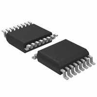
ADT7483AARQZ-REEL ON Semiconductor, ADT7483AARQZ-REEL Datasheet - Page 12

ADT7483AARQZ-REEL
Manufacturer Part Number
ADT7483AARQZ-REEL
Description
IC TEMP SENSOR/ALARM 3CH 16-QSOP
Manufacturer
ON Semiconductor
Datasheet
1.ADT7483AARQZ.pdf
(24 pages)
Specifications of ADT7483AARQZ-REEL
Function
Temp Monitoring System (Sensor)
Topology
ADC, Comparator, Multiplexer, Register Bank
Sensor Type
External & Internal
Sensing Temperature
-40°C ~ 125°C, External Sensor
Output Type
SMBus™
Output Alarm
Yes
Output Fan
Yes
Voltage - Supply
3 V ~ 3.6 V
Operating Temperature
-40°C ~ 125°C
Mounting Type
Surface Mount
Package / Case
16-QSOP
Lead Free Status / RoHS Status
Lead free / RoHS Compliant
ADT7483A
Configuration 1 Register
Table 8. Configuration 1 Register (Read Address = 0x03, Write Address = 0x09)
Bit
7
6
5
4
3
2
1
0
Configuration 2 Register
Table 9. Configuration 2 Register (Address = 0x24)
Bit
7
<6:0>
Conversion Rate/Channel Selector Register
The conversion rate/channel selector register is at Address 0x04
for reads, and Address 0x0A for writes. The four LSBs of this
register are used to program the conversion times from 15.5 ms
(Code 0x0A) to 16 seconds (Code 0x00). To program the
ADT7483A to perform continuous measurements, set the
conversion rate register to 0x0B. For example, a conversion rate
of 8 conversions/second means that beginning at 125 ms
intervals, the device performs a conversion on the local and the
remote temperature channels.
Mask
Mon/STBY
AL/TH
Remote 1/Remote 2
Temp Range
Mask R1
Mask R2
Mnemonic
Reserved
Mnemonic
Lock Bit
Reserved
Function
Setting this bit to 1 masks all ALERT s on the ALERT pin. Default = 0 = ALERT enabled. This applies only if Pin 13
is configured as ALERT , otherwise it has no effect.
Setting this bit to 1 places the ADT7483A in standby mode, that is, suspends all temperature measurements
(ADC). The SMBus remains active and values can be written to, and read from, the registers. THERM and ALERT
are also active in standby mode. Changes made to the limit registers in standby mode that affect the THERM or
ALERT outputs will cause these signals to be updated. Default = 0 = temperature monitoring enabled.
This bit selects the function of Pin 13. Default = 0 = ALERT . Setting this bit to 1 configures Pin 13 as the
THERM2 pin.
Reserved for future use.
Setting this bit to 1 enables the user to read the Remote 2 values from the Remote 1 registers.
Default = 0 = Remote 1 temperature values and limits are read from these registers. This bit is not lockable.
Setting this bit to 1 enables the extended temperature measurement range (−50°C to +150°C).
Default = 0 = 0°C to +127°C.
Setting this bit to 1 masks ALERT s due to the Remote 1 temperature exceeding a programmed limit.
Default = 0.
Setting this bit to 1 masks ALERT s due to the Remote 2 temperature exceeding a programmed limit.
Default = 0.
Function
Setting this bit to 1 locks all lockable registers to their current values. This prevents settings being
tampered with until the device is powered down. Default = 0.
Reserved for future use.
Rev. 1 | Page 12 of 24 | www.onsemi.com
This register can be written to and read back over the SMBus.
The default value of this register is 0x07, giving a rate of
8 conversions/second.
Bit 7 in this register can be used to disable averaging of the
temperature measurements. The ADT7483A can be configured
to take temperature measurements of either a single temperature
channel or all temperature channels. Bit 5 and Bit 4 can be used
to specify which temperature channel or channels are
measured.


