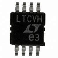
LTC6652BHMS8-1.25#PBF Linear Technology, LTC6652BHMS8-1.25#PBF Datasheet - Page 13

LTC6652BHMS8-1.25#PBF
Manufacturer Part Number
LTC6652BHMS8-1.25#PBF
Description
IC REF PREC LN 8-MSOP
Manufacturer
Linear Technology
Datasheet
1.LTC6652BHMS8-4.096PBF.pdf
(16 pages)
Specifications of LTC6652BHMS8-1.25#PBF
Reference Type
Series
Voltage - Output
1.25V
Tolerance
±0.1%
Temperature Coefficient
10ppm/°C
Voltage - Input
1.75 ~ 13.2 V
Number Of Channels
1
Current - Quiescent
350µA
Current - Output
16mA
Operating Temperature
-40°C ~ 125°C
Mounting Type
Surface Mount
Package / Case
8-MSOP, Micro8™, 8-uMAX, 8-uSOP,
Fixed / Adjust / Prog
Precision
Output Voltage (max)
1.25V
Reference Voltage Accuracy (max)
0.1
Line Regulation
50ppm/V
Load Regulation
250ppm/mA
Input Voltage (max)
13.2V
Operating Temp Range
-40C to 125C
Operating Temperature Classification
Automotive
Mounting
Surface Mount
Pin Count
8
Package Type
MSOP
Lead Free Status / RoHS Status
Lead free / RoHS Compliant
Current - Cathode
-
Lead Free Status / Rohs Status
Compliant
Available stocks
Company
Part Number
Manufacturer
Quantity
Price
Part Number:
LTC6652BHMS8-1.25#PBFLTC6652BHMS8-1.25
Manufacturer:
LINEAR/凌特
Quantity:
20 000
When operated within its specifi ed limits of V
and sourcing 5mA, the LTC6652-2.5 consumes just under
60mW at room temperature. At 125°C the quiescent cur-
rent will be slightly higher and the power consumption
APPLICATIONS INFORMATION
Figure 15. Output Voltage Shift Due to IR Refl ow
300
225
150
75
10
0
8
6
4
2
0
Figure 14. Lead-Free Refl ow Profi le
OUTPUT VOLTAGE SHIFT DUE TO IR REFLOW (%)
0
RAMP TO
150°C
T = 150°C
–0.014
T
S
= 190°C
T
2
S(MAX)
–0.006
= 200°C
4
380s
MINUTES
T
120s
L
= 217°C
0.002
T
P
6
= 260°C
130s
40s
0.010
30s
t
t
P
L
8
DOWN
RAMP
6652 F15
0.018
6652 F14
10
IN
= 13.2V
increases to just over 60mW. The power-derating curve
in Figure 16 shows the LTC6652-2.5 can safely dissipate
125mW at 125°C about half the maximum power con-
sumption of the package.
Figure 16. Maximum Recommended Dissipation for LTC6652
Figure 17. Typical Power Dissipation of the LTC6652
0.05
0.04
0.02
0.06
0.03
0.01
0.7
0.6
0.5
0.4
0.3
0.2
0.1
0
0
2
0
T
A
= 25°C
20
4
40
TEMPERATURE (°C)
5mA LOAD
6
60
NO LOAD
V
IN
8
(V)
80
10
100
12
120
LTC6652
6652 F17
6652 F16
140
14
13
6652fc


