ADR370ART-R2 Analog Devices Inc, ADR370ART-R2 Datasheet - Page 9
ADR370ART-R2
Manufacturer Part Number
ADR370ART-R2
Description
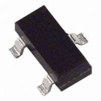
IC REF PREC LO PWR 2.048V SOT-23
Manufacturer
Analog Devices Inc
Datasheet
1.ADR370ARTZ-REEL7.pdf
(12 pages)
Specifications of ADR370ART-R2
Rohs Status
RoHS non-compliant
Reference Type
Series
Voltage - Output
2.048V
Tolerance
±0.5%
Temperature Coefficient
100ppm/°C
Voltage - Input
2.3 ~ 15 V
Number Of Channels
1
Current - Quiescent
72µA
Current - Output
5mA
Operating Temperature
-40°C ~ 125°C
Mounting Type
Surface Mount
Package / Case
SOT-23-3, TO-236-3, Micro3™, SSD3, SST3
Current - Cathode
-
Other names
ADR370ART-R2TR


APPLICATIONS INFORMATION
LOW COST NEGATIVE REFERENCE
A low cost negative reference can be obtained by leveraging the
current sinking capability of the ADR370. By simply tying the
V
the GND pin of the device, a negative voltage reference can be
obtained as shown in Figure 14. R
I
PRECISION NEGATIVE REFERENCE
Without using any matching resistors, a precision negative
reference can be obtained using the configuration shown in
Figure 15. The voltage difference between V
the ADR370 is 2.048 V. Because V
closes the loop by forcing the GND pin to be the negative
reference node. U2 should be a low offset voltage precision
op amp, such as the OP1177.
LOW COST CURRENT SOURCE
Figure 16 illustrates how a simple, low cost current source can
be configured using the ADR370. The load current, I
the sum of I
reference voltage generated by the ADR370 divided by R
The quiescent current, I
in I
SET
OUT
q
remains between 1 mA and 5 mA.
limits the use of this circuit to general-purpose applications.
I
terminal to ground and adding a bias resistor (R
SET
=
2.3V TO 12V
SET
. 2
R
048
–VREF
V
and the quiescent current, I
SET
DD
Figure 14. Low Cost Negative Reference
Figure 15. Precision Negative Reference
V
U1
V
V
q
IN
IN
R
, varies slightly with load. The variation
ADR370
ADR370
SET
GND
GND
V
SS
V
V
I
OUT
SET
OUT
OP1177
SET
OUT
should be chosen such that
is at virtual ground, U2
U2
+15V
–15V
q
. I
OUT
–VREF
SET
and GND of
is simply the
L
SET
, is simply
) to
SET
.
Rev. C | Page 9 of 12
(4)
PRECISION CURRENT SOURCE WITH ADJUSTABLE
OUTPUT
A precision current source can be implemented with the circuit
shown in Figure 17. By adding a mechanical or digital potenti-
ometer, this circuit becomes an adjustable current source. If a
digital potentiometer such as the
current is simply the voltage across Terminal B-to-Terminal W
of the digital potentiometer divided by R
where D is the decimal equivalent of the digital potentiometer
input code.
To optimize the resolution of this circuit, dual-supply op amps
should be used because the ground potential of the ADR370
can swing from −2.048 V at zero scale to V
potentiometer setting.
V
L
+ 2.5V < V
I
L
12V
=
Figure 17. Programmable 0 mA to 5 mA Current Source
R
DD
V
SET
REF
< V
–2.048V TO V
×
V
L
×
IN
+ 12V
256
Figure 16. Low Cost Current Source
ADR370
D
GND
V
V
IN
L
OUT
ADR370
I
OP1177
q
GND
= 65µA
AD5201
V
0V TO (2.048V + V
AD5201
OUT
+12V
–12V
B
A
SET
is used, the load
L
.
W
at full scale of the
R
SET
R
L
)
R
L
L
V
R
ADR370
L
SET
I
I
L
SET
I
L
V
L
=
2.048V
R
SET
(5)
Related parts for ADR370ART-R2
Image
Part Number
Description
Manufacturer
Datasheet
Request
R

Part Number:
Description:
±1.7g Dual-Axis IMEMS Accelerometer Evaluation Board
Manufacturer:
Analog Devices Inc
Datasheet:

Part Number:
Description:
Inertial Sensor Evaluation System
Manufacturer:
Analog Devices Inc
Datasheet:
Part Number:
Description:
Manufacturer:
Analog Devices Inc
Datasheet:
Part Number:
Description:
Manufacturer:
Analog Devices Inc
Datasheet:
Part Number:
Description:
Manufacturer:
Analog Devices Inc
Datasheet:
Part Number:
Description:
Manufacturer:
Analog Devices Inc
Datasheet:
Part Number:
Description:
Manufacturer:
Analog Devices Inc
Datasheet:
Part Number:
Description:
Manufacturer:
Analog Devices Inc
Datasheet:
Part Number:
Description:
Manufacturer:
Analog Devices Inc
Datasheet:
Part Number:
Description:
Manufacturer:
Analog Devices Inc
Datasheet:
Part Number:
Description:
Manufacturer:
Analog Devices Inc
Datasheet:
Part Number:
Description:
Manufacturer:
Analog Devices Inc
Datasheet:
Part Number:
Description:
Manufacturer:
Analog Devices Inc
Datasheet: