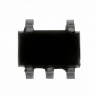
IRU431LCL5TR International Rectifier, IRU431LCL5TR Datasheet - Page 2

IRU431LCL5TR
Manufacturer Part Number
IRU431LCL5TR
Description
IC REG LDO LV ADJ SOT-23-5
Manufacturer
International Rectifier
Datasheet
1.IRU431-L3TR.pdf
(9 pages)
Specifications of IRU431LCL5TR
Reference Type
Shunt, Adjustable
Voltage - Output
1.24 ~ 15 V
Tolerance
±1%
Number Of Channels
1
Current - Cathode
80µA
Current - Output
10mA
Operating Temperature
0°C ~ 70°C
Mounting Type
Surface Mount
Package / Case
SOT-23-5, SC-74A, SOT-25
Lead Free Status / RoHS Status
Contains lead / RoHS non-compliant
Voltage - Input
-
Temperature Coefficient
-
Current - Quiescent
-
Available stocks
Company
Part Number
Manufacturer
Quantity
Price
Part Number:
IRU431LCL5TR
Manufacturer:
IR
Quantity:
20 000
IRU431L
ABSOLUTE MAXIMUM RATINGS
Input Voltage (V
Continuous Cathode Current Range .......................... -15mA to +15mA
Reference Current Range .......................................... -0.05mA to 15mA
Storage Temperature Range ...................................... -658C to 1508C
Operating Junction Temperature Range .....................
CAUTION: Stresses above those listed in "Absolute Maximum Ratings" may cause permanent damage to the device.
PACKAGE INFORMATION
ELECTRICAL SPECIFICATIONS
Unless otherwise specified, these specifications apply over T
Low duty cycle pulse testing is used which keeps junction and case temperatures equal to the ambient tempera-
ture.
PARAMETER
Reference Voltage
IRU431L
V
temperature range
Ratio of V
cathode voltage change
Reference Pin Current
I
temperature range
Minimum Cathode Current
Off State Cathode Current
Dynamic Impedance
Note 1: The dynamic impedance when V
fined as:
2
REF
REF
Anode
Deviation over full
?Z
Deviation over full
KA0
? =
3-PIN SOT-23 (L3)
REF
3
DV
JA
change to
DI
TOP VIEW
=336°C/W
K
KA
IN
) .................................................... 15V
2
1
Cathode
Ref
DV
V
I
REF(DEV)
SYM
REF
REF(DEV)
I
V
K(MIN)
Z
Ioff
REF
KA0
/DV
KA
Cathode
KA
I
I
V
I
I
I
V
V
V
V
V
I
K
K
K
K
K
K
=10mA, V
=10mA, V
=10mA, DV
=10mA, R1=10KV, R2=open
=10mA, R1=10KV, R2=open
=0.1 to 15mA, Note 1
KA
KA
KA
KA
KA
KA
=V
=V
=V
=6V, V
=10V, V
=15V, V
=V
NC
NC
REF
REF
REF
REF
5-PIN SOT-23 (L5)
1
2
3
is de-
TEST CONDITION
, I
, f<1KHz,
www.irf.com
JA
TOP VIEW
REF
K
=256 C/W
KA
REF
REF
KA
=10mA
=0V
=V
KA
=V
=0V
=0V
=V
REF
REF
When the device is operating with two external resistors
(See Figure 3), the total dynamic impedance of the cir-
cuit is given by:
08C to 1508C
REF
A
, T
=0 to 708C, Co =1mF. Typical values refer to T
5
4
?Z
A
to 6V
=258C
KA
Anode
Ref
? =
DV
DI
= ?Z
KA0
? 3 1 +
1.228
1.221
MIN
(
1.240
1.240
TYP
0.15
0.05
0.25
R1
R2
0.6
1.8
3.2
55
-1
6
)
1.252
1.259
MAX UNITS
0.75
0.4
80
10
-6
1
5
A
08/05/03
mV/V
Rev. 2.0
=258C.
mV
mA
mA
mA
mA
V
V


