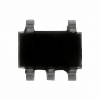
IRU431LCL5TR International Rectifier, IRU431LCL5TR Datasheet - Page 4

IRU431LCL5TR
Manufacturer Part Number
IRU431LCL5TR
Description
IC REG LDO LV ADJ SOT-23-5
Manufacturer
International Rectifier
Datasheet
1.IRU431-L3TR.pdf
(9 pages)
Specifications of IRU431LCL5TR
Reference Type
Shunt, Adjustable
Voltage - Output
1.24 ~ 15 V
Tolerance
±1%
Number Of Channels
1
Current - Cathode
80µA
Current - Output
10mA
Operating Temperature
0°C ~ 70°C
Mounting Type
Surface Mount
Package / Case
SOT-23-5, SC-74A, SOT-25
Lead Free Status / RoHS Status
Contains lead / RoHS non-compliant
Voltage - Input
-
Temperature Coefficient
-
Current - Quiescent
-
Available stocks
Company
Part Number
Manufacturer
Quantity
Price
Part Number:
IRU431LCL5TR
Manufacturer:
IR
Quantity:
20 000
IRU431L
APPLICATION INFORMATION
Output Voltage Setting
The IRU431L can be programmed to any voltages in the
range of 1.24 to 15V with the addition of R1 and R2
external resistors according to the following formula:
The IRU431L keeps a constant voltage of 1.240V be-
tween the Ref pin and Ground pin. By placing a resistor
R2 across these two pins a constant current flows
through R2, adding to the I
resistor producing a voltage equal to:
which will be added to the 1.240V to set the output volt-
age as shown in the above equation. Since the input
bias current of the Ref pin is 0.5mA max, it adds a very
small error to the output voltage and for most applica-
tions can be ignored. For example, in a typical 5V to
3.3V application where R2=1.21KV and R1=2KV the
error due to the I
the nominal set point.
Biasing Resistor (R
The biasing resistor R
limit the input current under the minimum input supply
and maximum load and biasing current.
4
V
IRU431L
IN
Vo = V
( )
Figure 3 - Typical application of the IRU431L
1.240
R2
for programming the output voltage.
R
KA
B
= V
3 R1 + I
ADJ
I
REF
K
is only 1mV which is about 0.03% of
B
3 1 +
) Selection
B
REF
is selected such that it does not
(
R1
R2
3 R1
REF
R1
R2
current and into the R1
)
Co
+ I
I
L
REF
R
L
3 R1
V
KA
= V
OUT
www.irf.com
An example is given below on how to properly select the
biasing resistor.
Assuming:
The maximum value for the biasing resistor is calcu-
lated using the following equations:
Assuming R1 = 2KV as before,
The maximum power dissipation of the resistor is calcu-
lated under the maximum supply voltage as follows:
R
I
I
I
R
Select R
P
Where:
V
P
P
V
V
V
I
Where:
V
I
I
I
I
B(MAX)
R
B(MAX)
L
L(MAX)
B(MAX)
K(MIN)
R
B(MAX)
B(MAX)
R
MAX
R
R
MIN
MAX
KA
MIN
= 10mA
=
= Current through R1
B
B
B
(MAX)
(MAX)
(MAX)
= 3.3V
3.3 - 1.24
= 4.5V
= Minimum supply voltage
= Maximum supply voltage
= 6V
= Maximum value for the minimum
= I
= Maximum load current
= 0.08 + 1.03 = 1.11mA
= Maximum bias current
=
=
cathode current spec
=
= Maximum R
=
K(MIN)
2
B
I
1.11 +10
4.5 - 3.3
(V
(6 - 3.3)
B(MAX)
= 100V
V
100
MAX
MIN
+ I
R
= 1.03mA
+ I
- V
B
- V
R
2
L(MAX)
KA
KA
= 73mW
= 108V
)
2
B
power dissipation
08/05/03
Rev. 2.0


