LM5035AMHX/NOPB National Semiconductor, LM5035AMHX/NOPB Datasheet - Page 24

LM5035AMHX/NOPB
Manufacturer Part Number
LM5035AMHX/NOPB
Description
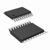
IC PWM BCK BST FLYBK INV 20TSSOP
Manufacturer
National Semiconductor
Series
PowerWise®r
Datasheet
1.LM5035AMHNOPB.pdf
(30 pages)
Specifications of LM5035AMHX/NOPB
Pwm Type
Voltage Mode
Number Of Outputs
1
Frequency - Max
1MHz
Duty Cycle
92%
Voltage - Supply
13 V ~ 105 V
Buck
Yes
Boost
Yes
Flyback
Yes
Inverting
Yes
Doubler
No
Divider
No
Cuk
No
Isolated
Yes
Operating Temperature
-40°C ~ 125°C
Package / Case
20-TSSOP Exposed Pad, 20-eTSSOP, 20-HTSSOP
Frequency-max
1MHz
For Use With
LM5035AEVAL - BOARD EVAL FOR LM5035ALM5035EVAL - BOARD EVALUATION LM5035
Lead Free Status / RoHS Status
Lead free / RoHS Compliant
Other names
LM5035AMHX
Available stocks
Company
Part Number
Manufacturer
Quantity
Price
Company:
Part Number:
LM5035AMHX/NOPB
Manufacturer:
NS/TI
Quantity:
1 250
Part Number:
LM5035AMHX/NOPB
Manufacturer:
NS/国半
Quantity:
20 000
www.national.com
Figure 15
Remote Thermal Protection using a thermistor (or multiple
thermistors) which may be located near the main heat
sources of the power supply. The negative temperature co-
efficient (NTC) thermistor is nearly logarithmic, and in this
example a 100kΩ thermistor with the β material constant of
4500 kelvins changes to approximately 2 kΩ at 130°C. Setting
R1 to one-third of this resistance (665Ω) establishes 130°C
as the desired trip point (for V
HICCUP MODE CURRENT LIMIT RESTART (RES)
The basic operation of the hiccup mode current limit restart is
described in the functional description. The delay time to
restart is programmed with the selection of the RES pin ca-
pacitor C
In the case of continuous cycle-by-cycle current limit detec-
tion at the CS pin, the time required for C
hiccup mode threshold is:
For example, if C
1.14 ms.
The cool down time, t2 is set by the soft-start capacitor (C
and the internal 1 µA SS current source, and is equal to:
RES
shows an application of the OVP comparator for
as illustrated in
RES
= 0.01 µF the time t1 is approximately
REF
Figure
= 5V). In a temperature band
15.
FIGURE 14. Latched Load Over-Voltage Protection
RES
FIGURE 15. Remote Thermal Protection
to reach the 2.5V
SS
)
24
from 20°C below to 20°C above the OVP threshold, the volt-
age divider is nearly linear with 25 mV per°C sensitivity.
R2 provides temperature hysteresis by raising the OVP com-
parator input by R2 x 23 µA. For example, if a 22kΩ resistor
is selected for R2, then the OVP pin voltage will increase by
22 kΩ x 23 µA = 506 mV. The NTC temperature must there-
fore fall by 506mV / 25mV per°C = 20°C before the LM5035A
switches from the standby mode to the normal mode.
If C
The soft-start time t3 is set by the internal 110 µA current
source, and is equal to:
If C
The time t2 provides a periodic cool-down time for the power
converter in the event of a sustained overload or short circuit.
This off time results in lower average input current and lower
power dissipation within the power components. It is recom-
SS
SS
= 0.01 µF t2 is
= 0.01 µF t3 is
≊
≊
10 ms.
363 µs.
30034138
30034137


