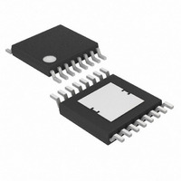
MAX15005AAUE+T Maxim Integrated Products, MAX15005AAUE+T Datasheet - Page 16

MAX15005AAUE+T
Manufacturer Part Number
MAX15005AAUE+T
Description
IC PWR SUPPLY CNTRLR 16-TSSOP
Manufacturer
Maxim Integrated Products
Datasheet
1.MAX15005BAUE.pdf
(27 pages)
Specifications of MAX15005AAUE+T
Pwm Type
Current Mode
Number Of Outputs
1
Frequency - Max
1MHz
Duty Cycle
81.5%
Voltage - Supply
4.5 V ~ 40 V
Buck
No
Boost
Yes
Flyback
Yes
Inverting
No
Doubler
No
Divider
Yes
Cuk
No
Isolated
Yes
Operating Temperature
-40°C ~ 125°C
Package / Case
16-TSSOP Exposed Pad, 16-eTSSOP, 16-HTSSOP
Frequency-max
1MHz
Duty Cycle (max)
80 %
Output Voltage
1.23 V to 100 V
Output Current
1000 mA
Mounting Style
SMD/SMT
Switching Frequency
15 KHz to 500 KHz
Maximum Operating Temperature
+ 125 C
Minimum Operating Temperature
- 40 C
Synchronous Pin
Yes
Topology
Boost, Flyback, Forward
Lead Free Status / RoHS Status
Lead free / RoHS Compliant
The input current for the boost converter is continuous
and the RMS ripple current at the input capacitor is low.
Calculate the minimum input capacitor value and maxi-
mum ESR using the following equations:
where:
V
FET plus the voltage drop across the inductor ESR. ΔI
is peak-to-peak inductor ripple current as calculated
above. ΔV
4.5V to 40V Input Automotive
Flyback/Boost/SEPIC Power-Supply Controllers
Figure 5. Application Schematic
16
DS
Input Capacitor Selection in Boost Configuration
is the total voltage drop across the external MOS-
______________________________________________________________________________________
Q
V
IN
is the portion of input ripple due to the
C
IN
C
ESR
Δ
C
IN
I
FF
L
RF
=
=
=
CT
RT
4 f
(V
Δ
V
×
Δ
IN
CF
ESR
L f
I
L
Δ
OUT
−
C
0.1μF
×
I
REG5
V
L
OUT
DS
×
11
10
×
6
D
) ) D
Δ
×
RTCT
COMP
FB
V
13
Q
SLOPE
REG5
4
C
MAX15004A/B
MAX15005A/B
SLOPE
D
VIN
1
9
SS
IN
C
OUT
L
V
CS
SS
CC
16
15
12
C
1μF
VIN
capacitor discharge and ΔV
to ESR of the capacitor. Assume the input capacitor rip-
ple contribution due to ESR (ΔV
charge (ΔV
ceramic and aluminum capacitors. During the convert-
er turn-on, a large current is drawn from the input
source especially at high output to input differential.
The MAX15004/MAX15005 are provided with a pro-
grammable soft-start, however, a large storage capaci-
tor at the input may be necessary to avoid chattering
due to finite hysteresis.
For the boost converter, the output capacitor supplies
the load current when the main switch is on. The
required output capacitance is high, especially at higher
duty cycles. Also, the output capacitor ESR needs to be
low enough to minimize the voltage drop due to the ESR
while supporting the load current. Use the following
equations to calculate the output capacitor, for a speci-
fied output ripple. All ripple values are peak-to-peak.
Output Capacitor Selection in Boost Configuration
C
CS
R
D
C
4.7μF
VCC
VCC
VCC
R
CS
Q
) is equal when using a combination of
PGND
Q
L
RS
D3
ESR
ESR
is the contribution due
C
OUT
) and capacitor dis-
V
RA
RB
OUT
18V


