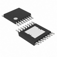
MAX5068AAUE+ Maxim Integrated Products, MAX5068AAUE+ Datasheet - Page 13

MAX5068AAUE+
Manufacturer Part Number
MAX5068AAUE+
Description
IC CNTRLR PWM CRNT MD 16TSSOP
Manufacturer
Maxim Integrated Products
Datasheet
1.MAX5068FAUE.pdf
(20 pages)
Specifications of MAX5068AAUE+
Pwm Type
Current Mode
Number Of Outputs
1
Frequency - Max
1.25MHz
Duty Cycle
50%
Voltage - Supply
10.8 V ~ 24 V
Buck
No
Boost
No
Flyback
Yes
Inverting
No
Doubler
No
Divider
No
Cuk
No
Isolated
Yes
Operating Temperature
-40°C ~ 125°C
Package / Case
16-TSSOP Exposed Pad, 16-eTSSOP, 16-HTSSOP
Frequency-max
1.25MHz
Duty Cycle (max)
50 %
Output Current
1000 mA
Mounting Style
SMD/SMT
Switching Frequency
25 KHz to 1250 KHz
Maximum Operating Temperature
+ 125 C
Minimum Operating Temperature
- 40 C
Synchronous Pin
Yes
Topology
Flyback, Forward
Lead Free Status / RoHS Status
Lead free / RoHS Compliant
Figure 6. Secondary-Side, Regulated, Isolated Power Supply
Assuming C1 > C3, calculate the value of R1 as follows:
where V
(23.6V max), V
age for the application (36V for telecom), and I
the V
For example:
High-Frequency, Current-Mode PWM Controller
IN
supply current at startup (90µA, max).
R
R
SUVR
1
1
I
C1
≅
≅
I
C
=
V
106
IN(MIN)
1
is the bootstrap UVLO wakeup level
V
IN MIN
IN
36
(
24
=
______________________________________________________________________________________
C2
C3
C4
µ
R2
R3
R4
V
with Accurate Programmable Oscillator
V x
A
I
500
V
C
)
1
SUVR
−
is the minimum input supply volt-
+
−
500
+
ms
12
2 2
90
.
0 5 .
I
V
START
µ
ms
µ
FLTINT
V
REG5
RT
DT
SYNC
AGND
C1
CC
×
A
F
R1
x V
C
=
=
MAX5068A
D2
1
SUVR
106
122 4
IN
µ
.
UVLO/EN
PGND
A
k
COMP
NDRV
HYST
Ω
CS
FB
START
R5
is
C5
To minimize power loss on this resistor, choose a high-
er value for R1 than the one calculated above (if a
longer startup time can be tolerated).
The above startup method is applicable to a circuit sim-
ilar to the one shown in
tiary winding has the same phase as the output
windings. Thus, the voltage on the tertiary winding at
any given time is proportional to the output voltage and
goes through the same soft-start period as the output
voltage. The minimum discharge time of C1 from 22V to
10V must be greater than the soft-start time (t
Use an external resistor at RT to program the MAX5068
internal oscillator frequency from 50kHz to 2.5MHz. The
MAX5068A/B output switching frequency is one-half of
the programmed oscillator frequency with a 50% duty
cycle. The MAX5068C/D/E/F output switching frequen-
cy is one-quarter of the programmed oscillator frequen-
cy with a 75% duty cycle.
R6
R
R7
HYST
Q1
R
R8
CS
R9
Oscillator/Switching Frequency
V
CC
R10
D1
PS2913
MAX8515
Figure 1. In this circuit, the ter-
VOUT
C10
R11
C7
C6
R12
R13
SS
).
13


