ISL6558IR Intersil, ISL6558IR Datasheet
ISL6558IR
Specifications of ISL6558IR
Available stocks


Related parts for ISL6558IR

ISL6558IR Summary of contents
Page 1
... CAUTION: These devices are sensitive to electrostatic discharge; follow proper IC Handling Procedures. | 1-888-INTERSIL or 1-888-468-3774 Intersil (and design registered trademark of Intersil Americas Inc. Copyright © Intersil Americas Inc. 2001-2005. All Rights Reserved All other trademarks mentioned are the property of their respective owners. ISL6558 FN9027 ...
Page 2
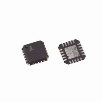
... ISL6558IR 5x5 QFN Tape and Reel ISL6558IRZ - 5x5 QFN (Pb-free) (Note) ISL6558IRZ 5x5 QFN Tape and Reel (Note) (Pb-free) ISL6558IRZA - 5x5 QFN (Pb-free) (See Note) ISL6558IRZA 5x5 QFN Tape and Reel (See Note) (Pb-free) ISL6558EVAL1 Evaluation Platform 1 (SOIC Package, ISL6558CB + HIP6601BCB) ...
Page 3
Block Diagram VSEN - + X 0 X1.15 AND FAULT COMP 0.8V REFERENCE FB DROOP 3 ISL6558 V PGOOD CC POWER-ON RESET (POR LATCH CLOCK AND S SAWTOOTH GENERATOR + ∑ ∑ ...
Page 4
Functional Pin Description NOTE: Pin numbers refer to the SOIC package. Check PINOUT diagrams for QFN pin numbers. VCC (Pin 1) Supplies all the power necessary to operate the chip. The IC starts to operate when the voltage on this ...
Page 5
Typical Application - 3 Phase Converter V = 0.8V )/R OUT DROOP COMP V CC VSEN PWM4 R OS PWM3 PGOOD PWM2 PWM1 PWM CONTROL ISL6558 ...
Page 6
... TEST CONDITIONS VCC = 5VDC 100kΩ ±1% T ISL6558CB, ISL6558CR 0°C to 70°C A ISL6558IB, ISL6558IR -40°C to 85°C A ISL6558CB, ISL6558CR 0°C to 70°C A ISL6558IB, ISL6558IR -40°C to 85° 100kΩ. ±1% T See Figure 3 Maximum voltage at FS/EN to disable controller 10K to ground 100pF 10K to ground ...
Page 7
... CHANNEL CONVERTER 7 ISL6558 = 5V -40°C to 85°C. Unless Otherwise Specified. (Continued TEST CONDITIONS VSEN Rising VSEN Falling I = 4mA PGOOD VSEN Rising, ISL6558CB, ISL6558CR, T VSEN Rising, ISL6558IB, ISL6558IR VSEN Falling after Overvoltage PWM1 PWM CIRCUIT V ERROR1 + CURRENT ISEN1 SENSING CURRENT AVERAGING ISEN2 ...
Page 8
Operation Figure 1 shows a simplified diagram of the voltage regulation and current control loops for a two-phase converter. Both voltage and current feedback are used to precisely regulate output voltage and tightly control phase currents the two ...
Page 9
FB pin, effectively creating the output voltage droop desired as a function of load current. SELECTING R AND output droop compensation is not required the DROOP pin must be left open. ...
Page 10
PWM1, 5V/DIV 0V PWM2, 5V/DIV 0V PWM3, 5V/DIV 0V 0V 1ms/DIV FIGURE 4. FOUR ACTIVE CHANNEL PWM DRIVE SIGNALS The PWM drive signals are switched out of phase. The PWM drive signal phase relationship is 360° divided by the number ...
Page 11
See Figure compared with an internally TOTAL generated overcurrent trip current, I TRIP trip current source is trimmed to 82.5µ the I level, then the controller forces all PWM outputs TRIP into three-state. This condition ...
Page 12
If the output voltage is not the same as the internal 0.8V reference, then a resistor divider scaled like the FB resistors is required as shown is Figure 8. ...
Page 13
IN VCC C PWM BP FS/EN COMP C C ISL6558 VSEN ISEN R FB ISLAND ON POWER PLANE LAYER FIGURE 9. PRINTED CIRCUIT BOARD POWER PLANES AND ISLANDS Component Selection Guidelines OUTPUT CAPACITOR SELECTION ...
Page 14
The total output ripple current can be determined from the curves in Figure 10. They provide the total ripple current as a function of duty cycle and number of active channels, normalized to the parameter K NORM V OUT K ...
Page 15
... Dimensions D2 and E2 are for the exposed pads which provide improved electrical and thermal performance. 8. Nominal dimensions are provided to assist with PCB Land Pattern Design efforts, see Intersil Technical Brief TB389. 9. Features and dimensions A2, A3, D1, E1, P & θ are present when Anvil singulation method is used and not present for saw singulation. 10. Compliant to JEDEC MO-220VHHC Issue I except for the " ...
Page 16
... Accordingly, the reader is cautioned to verify that data sheets are current before placing orders. Information furnished by Intersil is believed to be accurate and reliable. However, no responsibility is assumed by Intersil or its subsidiaries for its use; nor for any infringements of patents or other rights of third parties which may result from its use ...