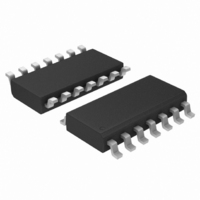
UC3843BVDR2 ON Semiconductor, UC3843BVDR2 Datasheet - Page 12

UC3843BVDR2
Manufacturer Part Number
UC3843BVDR2
Description
IC CTRLR CURRENT MODE HP 14SOIC
Manufacturer
ON Semiconductor
Datasheet
1.UC3842BDR2G.pdf
(21 pages)
Specifications of UC3843BVDR2
Pwm Type
Current Mode
Number Of Outputs
1
Frequency - Max
275kHz
Duty Cycle
96%
Voltage - Supply
8.2 V ~ 25 V
Buck
No
Boost
Yes
Flyback
Yes
Inverting
No
Doubler
No
Divider
No
Cuk
No
Isolated
Yes
Operating Temperature
-40°C ~ 105°C
Package / Case
14-SOIC (3.9mm Width), 14-SOL
Frequency-max
275kHz
Duty Cycle (max)
96 %
Output Voltage
4.9 V to 5.1 V
Output Current
1000 mA
Mounting Style
SMD/SMT
Switching Frequency
500 KHz
Operating Supply Voltage
30 V
Maximum Operating Temperature
+ 105 C
Fall Time
50 ns
Minimum Operating Temperature
- 40 C
Rise Time
50 ns
Synchronous Pin
No
Topology
Boost, Flyback, Forward
Lead Free Status / RoHS Status
Contains lead / RoHS non-compliant
Other names
UC3843BVDR2OSTR
Available stocks
Company
Part Number
Manufacturer
Quantity
Price
Company:
Part Number:
UC3843BVDR2G
Manufacturer:
TI
Quantity:
10 480
C
-
+
Virtually lossless current sensing can be achieved with the implementation of a
SENSEFET power switch. For proper operation during over-current conditions, a
reduction of the I
1.0M
Figure 26. Current Sensing Power MOSFET
5.0V Ref
8(14)
4(7)
2(3)
1(1)
Comp/Latch
pk(max)
S
R
t
Soft-Start
Q
Figure 24. Soft−Start Circuit
Control Circuitry Ground:
clamp level must be implemented. Refer to Figures 23 and 25.
≈ 3600C in mF
To Pin (9)
EA
+
R
R
-
+
(12)
Osc
1.0mA
Bias
V
(11)
(10)
(8)
(5)
CC
2R
G
R
1/4 W
S
R
-
+
D
M
5(9)
1.0V
SENSEFET
V
in
Then : V Pin 5 [ 0.075 I pk
V Pin 5 [
If: SENSEFET = MTP10N10M
R
5.0V Ref
K
To Input Source
S
S
Power Ground:
= 200
Return
S
R
r DM(on) ) R S
R S I pk r DS(on)
Q
http://onsemi.com
C
12
R
R
2
1
8(14)
t SoftStart + * In 1 *
4(7)
2(3)
1(1)
MPSA63
V Clamp [
Figure 25. Adjustable Buffered Reduction of
Figure 27. Current Waveform Spike Suppression
EA
R
R
-
+
+
R 2
R 1
The addition of the RC filter will eliminate instability caused by the leading
edge spike on the current waveform.
Clamp Level with Soft−Start
Osc
1.67
Bias
1.0 mA
) 1
5.0V Ref
Comp/Latch
3 V Clamp
2R
V C
R
S
R
Where: 0 ≤ V
V
C
Clamp
Q
1.0V
5(9)
R 1 ) R 2
-
+
R 1 R 2
5.0V Ref
Clamp
Comp/Latch
7(12)
≤ 1.0 V
+
-
S
R
V
CC
I pk(max) [
Q
7(11)
6(10)
5(8)
3(5)
+
-
C
R
V Clamp
7(12)
R S
V
CC
V
Q1
R
7(11)
6(10)
5(8)
3(5)
in
S
Q1
V
R
in
S


