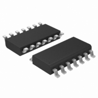
UC3843BVDR2 ON Semiconductor, UC3843BVDR2 Datasheet - Page 14

UC3843BVDR2
Manufacturer Part Number
UC3843BVDR2
Description
IC CTRLR CURRENT MODE HP 14SOIC
Manufacturer
ON Semiconductor
Datasheet
1.UC3842BDR2G.pdf
(21 pages)
Specifications of UC3843BVDR2
Pwm Type
Current Mode
Number Of Outputs
1
Frequency - Max
275kHz
Duty Cycle
96%
Voltage - Supply
8.2 V ~ 25 V
Buck
No
Boost
Yes
Flyback
Yes
Inverting
No
Doubler
No
Divider
No
Cuk
No
Isolated
Yes
Operating Temperature
-40°C ~ 105°C
Package / Case
14-SOIC (3.9mm Width), 14-SOL
Frequency-max
275kHz
Duty Cycle (max)
96 %
Output Voltage
4.9 V to 5.1 V
Output Current
1000 mA
Mounting Style
SMD/SMT
Switching Frequency
500 KHz
Operating Supply Voltage
30 V
Maximum Operating Temperature
+ 105 C
Fall Time
50 ns
Minimum Operating Temperature
- 40 C
Rise Time
50 ns
Synchronous Pin
No
Topology
Boost, Flyback, Forward
Lead Free Status / RoHS Status
Contains lead / RoHS non-compliant
Other names
UC3843BVDR2OSTR
Available stocks
Company
Part Number
Manufacturer
Quantity
Price
Company:
Part Number:
UC3843BVDR2G
Manufacturer:
TI
Quantity:
10 480
From V
O
R
R
i
d
MPS3904
R
Slope
C
f
C
T
R
8(14)
The buffered oscillator ramp can be resistively summed with either the voltage
feedback or current sense inputs to provide slope compensation.
4(7)
2(3)
1(1)
T
R
Error Amp compensation circuit for stabilizing any current mode topology except for boost and flyback
converters operating with continuous inductor current.
f
C
Figure 32. Error Amplifier Compensation
From V
R
p
Error Amp compensation circuit for stabilizing current mode boost and flyback
topologies operating with continuous inductor current.
p
O
- 3.0m
EA
Figure 33. Slope Compensation
R
R
R
From V
R
i
R
R
d
d
i
R
+
f
≥ 8.8 k
Osc
O
1.0mA
Bias
C
C
http://onsemi.com
f
f
2R
1(1)
1(1)
2(3)
2(3)
R
R
R
f
f
-
+
5(9)
14
1.0V
2.5V
2.5V
-m
5.0V Ref
EA
EA
m
Comp/Latch
+
+
S
R
1.0mA
1.0mA
Q
2R
2R
R
R
+
-
5(9)
5(9)
7(12)
36V
7(11)
6(10)
5(8)
3(5)
V
CC
R
V
S
in


