UC3843BNG ON Semiconductor, UC3843BNG Datasheet - Page 9
UC3843BNG
Manufacturer Part Number
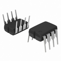
UC3843BNG
Description
IC CTLR CURRENT MODE 8-DIP
Manufacturer
ON Semiconductor
Specifications of UC3843BNG
Pwm Type
Current Mode
Number Of Outputs
1
Frequency - Max
275kHz
Duty Cycle
96%
Voltage - Supply
8.2 V ~ 25 V
Buck
No
Boost
Yes
Flyback
Yes
Inverting
No
Doubler
No
Divider
No
Cuk
No
Isolated
Yes
Operating Temperature
0°C ~ 70°C
Package / Case
8-DIP (0.300", 7.62mm)
Frequency-max
275kHz
Duty Cycle (max)
96 % (Typ)
Output Voltage
4.9 V to 5.1 V
Output Current
1000 mA (Max)
Mounting Style
Through Hole
Switching Frequency
500 KHz
Operating Supply Voltage
30 V
Maximum Operating Temperature
70 C
Fall Time
50 ns
Minimum Operating Temperature
0 C
Rise Time
50 ns
Synchronous Pin
No
Topology
Boost or Flyback or Forward
Number Of Pwm Outputs
1
On/off Pin
No
Adjustable Output
No
Switching Freq
500kHz
Operating Supply Voltage (max)
30V
Operating Temperature Classification
Commercial
Mounting
Through Hole
Pin Count
8
Package Type
PDIP
Lead Free Status / RoHS Status
Lead free / RoHS Compliant
Other names
UC3843BNGOS
Available stocks
Company
Part Number
Manufacturer
Quantity
Price
Company:

Part Number:
UC3843BNG
Manufacturer:
ON
Quantity:
11 000
Company:
Part Number:
UC3843BNG
Manufacturer:
ON Semiconductor
Quantity:
3 300
Part Number:
UC3843BNG
Manufacturer:
ON/安森美
Quantity:
20 000
Part Number:
UC3843BNG ON
Manufacturer:
ON/安森美
Quantity:
20 000


Error Amplifier
inverting input and output is provided. It features a typical
DC voltage gain of 90 dB, and a unity gain bandwidth of
1.0 MHz with 57 degrees of phase margin (Figure 8). The
non−inverting input is internally biased at 2.5 V and is not
pinned out. The converter output voltage is typically divided
down and monitored by the inverting input. The maximum
input bias current is −2.0 mA which can cause an output
voltage error that is equal to the product of the input bias
current and the equivalent input divider source resistance.
loop compensation (Figure 33). The output voltage is offset
by two diode drops (≈1.4 V) and divided by three before it
connects to the non−inverting input of the Current Sense
Comparator. This guarantees that no drive pulses appear at
the Output (Pin 6) when pin 1 is at its lowest state (V
This occurs when the power supply is operating and the load
is removed, or at the beginning of a soft−start interval
(Figures 25, 26). The Error Amp minimum feedback
resistance is limited by the amplifier’s source current
(0.5 mA) and the required output voltage (V
comparator’s 1.0 V clamp level:
Current Sense Comparator and PWM Latch
controller, whereby output switch conduction is initiated by
the oscillator and terminated when the peak inductor current
reaches the threshold level established by the Error
Amplifier Output/Compensation (Pin 1). Thus the error
signal controls the peak inductor current on a
cycle−by−cycle basis. The Current Sense Comparator PWM
Latch configuration used ensures that only a single pulse
A fully compensated Error Amplifier with access to the
The Error Amp Output (Pin 1) is provided for external
The UC3842B, UC3843B operate as a current mode
R
f(min)
≈
3.0 (1.0 V) + 1.4 V
0.5 mA
= 8800 W
OH
) to reach the
http://onsemi.com
OL
).
9
appears at the Output during any given oscillator cycle. The
inductor current is converted to a voltage by inserting the
ground−referenced sense resistor R
source of output switch Q1. This voltage is monitored by the
Current Sense Input (Pin 3) and compared to a level derived
from the Error Amp Output. The peak inductor current under
normal operating conditions is controlled by the voltage at
pin 1 where:
supply output is overloaded or if output voltage sensing is
lost. Under these conditions, the Current Sense Comparator
threshold will be internally clamped to 1.0 V. Therefore the
maximum peak switch current is:
becomes desirable to reduce the internal clamp voltage in
order to keep the power dissipation of R
level. A simple method to adjust this voltage is shown in
Figure 24. The two external diodes are used to compensate
the internal diodes, yielding a constant clamp voltage over
temperature. Erratic operation due to noise pickup can result
if there is an excessive reduction of the I
voltage.
waveform can usually be observed and may cause the power
supply to exhibit an instability when the output is lightly
loaded. This spike is due to the power transformer
interwinding capacitance and output rectifier recovery time.
The addition of an RC filter on the Current Sense Input with
a time constant that approximates the spike duration will
usually eliminate the instability (refer to Figure 28).
Abnormal operating conditions occur when the power
When designing a high power switching regulator it
A narrow spike on the leading edge of the current
I
pk
I
pk(max)
=
V
(Pin 1)
=
3 R
− 1.4 V
1.0 V
S
R
S
S
in series with the
S
to a reasonable
pk(max)
clamp
Related parts for UC3843BNG
Image
Part Number
Description
Manufacturer
Datasheet
Request
R

Part Number:
Description:
ON Semiconductor [VOLTAGE REGULATOR]
Manufacturer:
ON Semiconductor
Datasheet:
Part Number:
Description:
357-036-542-201 CARDEDGE 36POS DL .156 BLK LOPRO
Manufacturer:
ON Semiconductor
Datasheet:
Part Number:
Description:
357-036-542-201 CARDEDGE 36POS DL .156 BLK LOPRO
Manufacturer:
ON Semiconductor
Datasheet:
Part Number:
Description:
357-036-542-201 CARDEDGE 36POS DL .156 BLK LOPRO
Manufacturer:
ON Semiconductor
Datasheet:
Part Number:
Description:
357-036-542-201 CARDEDGE 36POS DL .156 BLK LOPRO
Manufacturer:
ON Semiconductor
Datasheet:
Part Number:
Description:
357-036-542-201 CARDEDGE 36POS DL .156 BLK LOPRO
Manufacturer:
ON Semiconductor
Datasheet:
Part Number:
Description:
357-036-542-201 CARDEDGE 36POS DL .156 BLK LOPRO
Manufacturer:
ON Semiconductor
Datasheet:
Part Number:
Description:
357-036-542-201 CARDEDGE 36POS DL .156 BLK LOPRO
Manufacturer:
ON Semiconductor
Datasheet:
Part Number:
Description:
357-036-542-201 CARDEDGE 36POS DL .156 BLK LOPRO
Manufacturer:
ON Semiconductor
Datasheet:
Part Number:
Description:
357-036-542-201 CARDEDGE 36POS DL .156 BLK LOPRO
Manufacturer:
ON Semiconductor
Datasheet:
Part Number:
Description:
357-036-542-201 CARDEDGE 36POS DL .156 BLK LOPRO
Manufacturer:
ON Semiconductor
Datasheet:
Part Number:
Description:
Manufacturer:
ON Semiconductor
Datasheet:
Part Number:
Description:
Manufacturer:
ON Semiconductor
Datasheet:
Part Number:
Description:
Manufacturer:
ON Semiconductor
Datasheet: