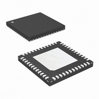
ISL6266AIRZ Intersil, ISL6266AIRZ Datasheet - Page 3

ISL6266AIRZ
Manufacturer Part Number
ISL6266AIRZ
Description
IC CORE CTRLR 2PHASE 48-QFN
Manufacturer
Intersil
Datasheet
1.ISL6266HRZ.pdf
(30 pages)
Specifications of ISL6266AIRZ
Applications
Converter, Intel IMVP-6
Voltage - Input
5 ~ 25 V
Number Of Outputs
1
Voltage - Output
0.3 ~ 1.5 V
Operating Temperature
-40°C ~ 100°C
Mounting Type
Surface Mount
Package / Case
48-VQFN
Lead Free Status / RoHS Status
Lead free / RoHS Compliant
Available stocks
Company
Part Number
Manufacturer
Quantity
Price
Company:
Part Number:
ISL6266AIRZ
Manufacturer:
Intersil
Quantity:
166
Electrical Specifications
Absolute Maximum Ratings
Supply Voltage (V
Battery Voltage (V
Boot Voltage (BOOT) . . . . . . . . . . . . . . . . . . . . . . . . . . -0.3V to +33V
Boot to Phase Voltage (BOOT to PHASE). . . . . . -0.3V to +7V (DC)
Phase Voltage (PHASE) . . . . . . . . . -7V (<20ns Pulse Width, 10µJ)
UGATE Voltage (UGATE) . . . . . . . . . . PHASE -0.3V (DC) to BOOT
LGATE Voltage (LGATE) . . . . . . . . . . . -0.3V (DC) to (VDD + 0.3V)
All Other Pins . . . . . . . . . . . . . . . . . . . . . . . . . -0.3V to (VDD + 0.3V)
Open Drain Outputs, PGOOD, VR_TT# . . . . . . . . . . . -0.3V to +7V
CAUTION: Do not operate at or near the maximum ratings listed for extended periods of time. Exposure to such conditions may adversely impact product reliability and
result in failures not covered by warranty.
NOTES:
INPUT POWER SUPPLY
+5V Supply Current
+3.3V Supply Current
Battery Supply Current at VIN pin
POR (Power-On Reset) Threshold
SYSTEM AND REFERENCES
System Accuracy ( ISL6266AHRZ)
System Accuracy (ISL6266AIRZ)
RBIAS Voltage
Boot Voltage
Output Voltage Range
VID Off State
1. θ
2. For θ
. . . . . . . . . . . . . . . . . . . . . . . . . . . . . . . . . . . -0.3V to +9V (<10ns)
. . . . . . . . . . . . . .PHASE-5V (<20ns Pulse Width, 10µJ) to BOOT
. . . . . . . . . . . . . .-2.5V (<20ns Pulse Width, 5µJ) to (VDD + 0.3V)
Tech Brief TB379.
JA
is measured in free air with the component mounted on a high effective thermal conductivity test board with “direct attach” features. See
JC
PARAMETER
, the “case temp” location is the center of the exposed metal pad on the package underside.
DD
IN
) . . . . . . . . . . . . . . . . . . . . . . . . . . . . . . . . +28V
) . . . . . . . . . . . . . . . . . . . . . . . . . -0.3V to +7V
3
V
DD
= 5V, T
(V
V
V
(V
SYMBOL
CC_CORE
CC_CORE
CC_CORE
R
V
%Error
%Error
cc_core
(max)
POR
POR
(min)
I
I
RBIAS
BOOT
I
VDD
3V3
VIN
A
= -40°C to +100°C, unless otherwise specified.
r
f
)
)
ISL6266, ISL6266A
VR_ON = 3.3V
VR_ON = 0V
No load on CLK_EN#
VR_ON = 0V, V
V
V
No load, closed loop, active mode,
T
VID = 0.5V to 0.7375V
VID = 0.3V to 0.4875V
No load, closed loop, active mode,
VID = 0.75V to 1.5V
VID = 0.5V to 0.7375V
VID = 0.3V to 0.4875V
R
VID = [0000000]
VID = [1100000]
VID = [1111111]
A
DD
DD
RBIAS
= 0°C to +100°C, VID = 0.75V to 1.5V
Rising
Falling
= 147kΩ
TEST CONDITIONS
IN
= 25V
Thermal Information
Thermal Resistance (Typical)
Maximum Junction Temperature . . . . . . . . . . . . . . . . . . . . . +150°C
Maximum Storage Temperature Range . . . . . . . . . -65°C to +150°C
Pb-free Reflow Profile . . . . . . . . . . . . . . . . . . . . . . . . .see link below
Recommended Operating Conditions
Supply Voltage, V
Battery Voltage, V
Ambient Temperature . . . . . . . . . . . . . . . . . . . . . . -40°C to +100°C
Junction Temperature . . . . . . . . . . . . . . . . . . . . . . -40°C to +125°C
QFN Package (Notes 1, 2). . . . . . . . . .
http://www.intersil.com/pbfree/Pb-FreeReflow.asp
DD
IN
. . . . . . . . . . . . . . . . . . . . . . . . . . . . +5V to 25V
. . . . . . . . . . . . . . . . . . . . . . . . . . . . . +5V ±5%
(Note 4)
1.188
1.45
MIN
-0.5
-0.8
-15
-10
-18
4.0
-8
TYP
4.35
4.15
1.47
5.1
1.2
1.5
0.3
0
θ
JA
29
°C/W
(Note 4) UNITS
1.212
MAX
1.49
5.7
4.5
0.5
0.8
15
10
18
1
1
1
8
June 14, 2010
θ
JC
FN6398.3
4.5
°C/W
mA
mV
mV
mV
mV
µA
µA
µA
%
%
V
V
V
V
V
V
V


