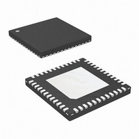
ISL6262ACRZ Intersil, ISL6262ACRZ Datasheet - Page 17

ISL6262ACRZ
Manufacturer Part Number
ISL6262ACRZ
Description
IC CORE CTRLR 2PHASE 48-QFN
Manufacturer
Intersil
Datasheet
1.ISL6262ACRZ.pdf
(28 pages)
Specifications of ISL6262ACRZ
Applications
Controller, Intel IMVP-6
Voltage - Input
5 ~ 25 V
Number Of Outputs
1
Voltage - Output
0.3 ~ 1.5 V
Operating Temperature
-10°C ~ 100°C
Mounting Type
Surface Mount
Package / Case
48-VQFN
Lead Free Status / RoHS Status
Lead free / RoHS Compliant
Available stocks
Company
Part Number
Manufacturer
Quantity
Price
Part Number:
ISL6262ACRZ
Manufacturer:
INTERSIL
Quantity:
20 000
Company:
Part Number:
ISL6262ACRZ-T
Manufacturer:
ISL
Quantity:
2 395
Company:
Part Number:
ISL6262ACRZ-T
Manufacturer:
INTERSIL
Quantity:
20 562
Part Number:
ISL6262ACRZ-T
Manufacturer:
INTERSIL
Quantity:
20 000
analog of the total inductor current. This voltage is used as
an input to a differential amplifier to achieve the IMVP-6+
load line, and also as the input to the overcurrent protection
circuit.
When using inductor DCR current sensing, a single NTC
element is used to compensate the positive temperature
coefficient of the copper winding thus maintaining the
load-line accuracy.
In addition to monitoring the total current (used for DROOP
and overcurrent protection), the individual channel average
currents are also monitored and used for balancing the load
between channels. The IBAL circuit will adjust the channel
pulse-widths up or down relative to the other channel to
cause the voltages presented at the ISEN pins to be equal.
The ISL6262A controller can be configured for two-channel
operation, with the channels operating 180° apart. The
channel PWM frequency is determined by the value of
R
Figure 33. Input and output ripple frequencies will be the
channel PWM frequency multiplied by the number of active
channels.
High Efficiency Operation Mode
The ISL6262A has several operating modes to optimize
efficiency. The controller's operational modes are designed
to work in conjunction with the Intel® IMVP-6+ control
signals to maintain the optimal system configuration for all
IMVP-6+ conditions. These operating modes are established
by the IMVP-6+ control signal inputs such as PSI#,
DPRSLPVR, and DPRSTP# as shown in Table 2. At high
current levels, the system will operate with both phases fully
active, responding rapidly to transients and deliver the
maximum power to the load. At reduced load-current levels,
one of the phases may be idled. This configuration will
minimize switching losses, while still maintaining transient
response capability. At the lowest current levels, the
controller automatically configures the system to operate in
single-phase automatic-DCM mode, thus achieving the
highest possible efficiency. In this mode of operation, the
lower MOSFET will be configured to automatically detect
and prevent discharge current flowing from the output
COMPLIANT LOGIC
FSET
OTHER LOGIC
Intel IMVP-6+
COMMANDS
connected to pin VW as shown in Figure 32 and
TABLE 2. CONTROL SIGNAL TRUTH TABLES FOR OPERATION MODES OF ISL6262A IN TWO-PHASE DESIGN
DPRSLPVR
0
0
1
1
0
0
1
1
17
DPRSTP#
1
1
0
0
0
0
1
1
PSI#
1
0
1
0
1
0
1
0
ISL6262A
2-phase CCM
1-phase CCM
1-phase diode emulation
1-phase diode emulation
2-phase CCM
1-phase CCM
2-phase CCM
1-phase CCM
PHASE OPERATION MODES
capacitor through the inductors, and the switching frequency
will be proportionately reduced, thus greatly reducing both
conduction and switching losses. If ISEN2 is pulled to 5V, the
ISL6262A operates at 1-phase-only mode. The ISL6262A
always enables the diode emulation mode of phase 1 in
always-1-phase configuration.
Smooth mode transitions are facilitated by the R
Technology™, which correctly maintains the internally
synthesized ripple currents throughout mode transitions. The
controller is thus able to deliver the appropriate current to the
load throughout mode transitions. The controller contains
embedded mode-transition algorithms that maintain
voltage-regulation for all control signal input sequences and
durations.
Mode-transition sequences often occur in concert with VID
changes; therefore the timing of the mode transitions of
ISL6262A has been carefully designed to work in concert
with VID changes. For example, transitions into single-phase
will be delayed until the VID induced voltage ramp is
complete. This allows the associated output capacitor
charging current to be shared by both inductor paths. While
in single-phase automatic-DCM mode, VID changes will
initiate an immediate return to two-phase CCM mode. This
ensures that both inductor paths share the output capacitor
charging current and are fully active for the subsequent load
current increases.
spurious control signal glitches from resulting in unwanted
mode transitions. Control signals of less than two switching
periods do not result in phase-idling. Signals of less than
seven switching periods do not result in implementation of
automatic-DCM mode.
While transitioning to single-phase operation, the controller
smoothly transitions current from the idling-phase to the
active-phase, and detects the idling-phase zero-current
condition. During transitions into automatic-DCM or
forced-CCM mode, the timing is carefully adjusted to
eliminate output voltage excursions. When a phase is
added, the current balance between phases is quickly
restored.
The controller contains internal counters that prevent
Active mode
Active mode
Deeper sleep mode
Deeper sleep mode
EXPECTED CPU MODE
December 23, 2008
3
FN6343.1


