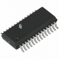
FAN5236QSC Fairchild Semiconductor, FAN5236QSC Datasheet - Page 11

FAN5236QSC
Manufacturer Part Number
FAN5236QSC
Description
IC CTRLR DDR/PWM DUAL HE 28QSOP
Manufacturer
Fairchild Semiconductor
Specifications of FAN5236QSC
Applications
Controller, Mobile-Friendly DDR
Voltage - Input
5 ~ 24 V
Number Of Outputs
2
Voltage - Output
0.9 ~ 5 V
Operating Temperature
-10°C ~ 85°C
Mounting Type
Surface Mount
Package / Case
28-QSOP
Operating Temperature Range
- 10 C to + 85 C
Mounting Style
SMD/SMT
Lead Free Status / RoHS Status
Lead free / RoHS Compliant
Other names
FAN5236QSC_NL
FAN5236QSC_NL
FAN5236QSC_NL
Available stocks
Company
Part Number
Manufacturer
Quantity
Price
Part Number:
FAN5236QSC
Manufacturer:
FAIRCHILD/ن»™ç«¥
Quantity:
20 000
Company:
Part Number:
FAN5236QSCX
Manufacturer:
FAIRCHIL
Quantity:
17 500
Part Number:
FAN5236QSCX
Manufacturer:
FAIRCHILD/ن»™ç«¥
Quantity:
20 000
FAN5236
Hysteretic Mode
Conversely, the transition from Hysteretic mode to PWM
mode occurs when the SW node is negative for 8 consecutive
cycles.
A sudden increase in the output current will also cause a
change from hysteretic to PWM mode. This load increase
causes an instantaneous decrease in the output voltage due to
the voltage drop on the output capacitor ESR. If the load
causes the output voltage (as presented at VSNS) to drop
below the hysteretic regulation level (20mV below VREF),
the mode is changed to PWM on the next clock cycle.
In hysteretic mode, the PWM comparator and the error
amplifier that provide control in PWM mode are inhibited
and the hysteretic comparator is activated. In hysteretic
mode the low side MOSFET is operated as a synchronous
rectifier, where the voltage across ( V
and it is switched off when V
flowing back from the load) allowing the diode to block
reverse conduction.
The hysteretic comparator initiates a PFM signal to turn on
HDRV at the rising edge of the next oscillator clock, when
the output voltage (at VSNS) falls below the lower threshold
(10mV below VREF) and terminates the PFM signal when
VSNS rises over the higher threshold (5mV above VREF).
REV. 1.1.9 7/12/04
C
SS
VSEN
SS
300K
Reference and
Soft Start
DS(ON)
ILIM det.
1.5M
TO PWM COMP
goes positive (current
DS(ON)
0.17pf
17pf
Figure 11. Current Limit / Summing Circuits
) it is monitored,
4.14K
2.5V
ILIM*11.2
I2 =
The switching frequency is primarily a function of:
1.
2.
3.
A transition back to PWM (Continuous Conduction Mode or
CCM) mode occurs when the inductor current rises suffi-
ciently to stay positive for 8 consecutive cycles. This occurs
when:
where V
series resistance of C
Because of the different control mechanisms, the value of the
load current where transition into CCM operation takes place
is typically higher compared to the load level at which transi-
tion into hysteretic mode occurs. Hysteretic mode can be
disabled by setting the FPWM pin low.
Spread between the two hysteretic thresholds
I
Output Inductor and Capacitor ESR
ISNS
LOAD
I
LOAD CCM
HYSTERESIS
V to I
0.9V
ILIM
S/H
ISNS
=
OUT
-------------------------------------- -
= 15mV and ESR is the equivalent
V
HYSTERESIS
.
2 ESR
in +
in –
PRODUCT SPECIFICATION
LDRV
PGND
ISNS
ILIM
R
R
SENSE
ILIM
(3)
11


