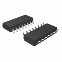
MIC9131BM Micrel Inc, MIC9131BM Datasheet - Page 11

MIC9131BM
Manufacturer Part Number
MIC9131BM
Description
IC CTRLR DC-DC PWM HV HS 16-SOIC
Manufacturer
Micrel Inc
Datasheet
1.MIC9131YM.pdf
(19 pages)
Specifications of MIC9131BM
Applications
Controller, Telecom
Voltage - Input
9 ~ 18 V
Number Of Outputs
1
Voltage - Output
4.7 ~ 5 V
Operating Temperature
-40°C ~ 125°C
Mounting Type
Surface Mount
Package / Case
16-SOIC (3.9mm Width)
Lead Free Status / RoHS Status
Contains lead / RoHS non-compliant
Available stocks
Company
Part Number
Manufacturer
Quantity
Price
V
The V
a 1.21V internal bandgap reference. As V
turn-on threshold, it disables the V
circuit. Once above the turn-on threshold, hysteresis prevents
the lockout circuit from disabling the IC until the V
falls below the lower threshold.
Line Undervoltage Circuit (UVLO)
The line voltage is monitored by an external resistor divider
and fed into the negative input of the line UVLO comparator.
As the comparator trip point is exceeded, the line UVLO circuit
is disabled. Hysteresis built into the comparator prevents the
circuit from toggling on an off in the presence of noise or a
high input line impedance.
The line voltage turn-on trip point is:
where: V
where: V
The MIC9131 will be disabled when the line voltage drops
back down to:
August 2006
MIC9131
CC
Undervoltage Lockout
CC
V
The line hysteresis is equal to:
V
75mV.
V
V
(
voltage is internally divided down and compared to
LINE_ON
HYSTERESIS
V
THRESHOLD
HYST
HYSTERESIS
LINE_OFF
THRESHOLD
comparator reference, typically 1.21V.
voltage
is the internal hysteresis level, typically
V
=
IN
R2
V
=
R1
THRESHOLD
V
=
LINE_ON
−
is the voltage level of the internal
V
is the hysteresis of the line input
HYST
V
UVLO
A
HYST
V
GND
CC
×
−
11
13
×
2
)
R1 R2
V
×
R1 R2
HYTERESIS
R2
R1 R2
+
R2
+
R2
+
CC
1.21V
undervoltage lockout
=
Figure 4: UVLO and Soft Start Circuits
CC
rises above the
CC
voltage
VCC
UVLO
LINE
UVLO
11
MIC9131
Enable
A low level on the enable pin turns off all the functions of the
MIC9131 and places it in a low quiescent current state. The
output driver is in a low state. When the enable pin is pulled
high, the MIC9131 goes through its normal start up sequence
including undervoltage lock out and soft start. When not used,
the pin should be connected to V
Oscillator Block
An external resistor and capacitor set the oscillator frequency.
The MIC9131 contains an internal divide-by-four circuit that
limits the maximum duty cycle at the gate drive to 75%. The
oscillator frequency of the MIC9131 is four times the output
switching frequency.
Oscillator Pin
The operation of the oscillator is shown in Figure 5. The volt-
age waveform at the OSC pin is a sawtooth whose amplitude
increases as capacitor Cosc is charged up through R
the 5V
comparator upper threshold, C
zero volts by an internal MOSFET. After a brief delay, typi-
cally 75ns, the internal MOSFET is turned off and the C
charges, repeating the cycle. Figure 5 show the relationship
between the oscillator and gate drive waveforms. The delays
in the IC force the duty cycle of the gate drive signal to be
slightly less than 75% duty cycle.
3V, the design equations simplify to:
For V
UVLO
BIAS
BIAS
t
Charging
Discharging
t
CHARGE
DISCHARGE
. When the OSC pin voltage reaches the internal
= 5V and a peak oscillator waveform voltage of
S
R
RESET
SET
=
0 92
≈
.
40
/Q
Q
×
×
R
C
PGND
t
t
×
15
C
OSC
t
4µA
CC
is quickly discharged to
.
5V
12
16
SS
OUT
M9999-080206
Micrel, Inc.
OSC
from
OSC


