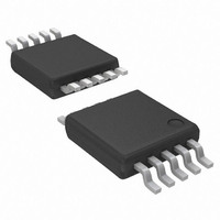
AP6714M10G-13 Diodes Inc, AP6714M10G-13 Datasheet

AP6714M10G-13
Specifications of AP6714M10G-13
Available stocks
Related parts for AP6714M10G-13
AP6714M10G-13 Summary of contents
Page 1
... Ordering Information Package M10 : MSOP-10L Package Device Code AP6714M10G-13 M10 Notes Directive 2002/95/EC (RoHS). All applicable RoHS exemptions applied, see EU Directive 2002/95/EC Annex Notes. 2. Pad layout as shown on Diodes Inc. suggested pad layout document AP02001, which can be found on our website at http://www.diodes.com/datasheets/ap02001.pdf. ...
Page 2
... FB 4 Channel Feedback Pin REF 5 Internal Reference Voltage SGND 6 Signal Ground PGND 7 Power Ground OCP 8 Over Current Protection Pin OUT 10 Boost Output Pin AP6714 Rev. 4 1.8MHz SYNCHRONOUS BOOST CONVERTER 10 OUT OCP 7 PGND SGND 6 Description www.diodes.com AP6714 FEBRUARY 2009 © Diodes Incorporated ...
Page 3
... Thermal - shutdown OCP Comparator + Parameter Parameter (Note www.diodes.com AP6714 OUT ZCR + - LX OCP PGND - 0.16V Rating Unit 3 250 -0.3 to +6.5 -0.3 to (OUT + 0.3) 1.6 -0 0.3) CC 850 mW -40 to +125 -65 to +150 Rating Unit -40 to +85 0.9 to 5.5 1.8 to 5.5 FEBRUARY 2009 © Diodes Incorporated ...
Page 4
... AP6714 Min Typ. Max Unit - 0.5 1 µA - 150 300 µA 1.23 1.255 V o ppm 4 1 1800 2200 KHz o 50 100 ppm/ C 0.01 +100 µ µA - 200 - mΩ - 300 - 1.2 1.4 1 150 - 0 161 C C/W FEBRUARY 2009 © Diodes Incorporated ...
Page 5
... TOP OUT FB R BOTTOM : 100 KΩ. Supply Current vs. Temperature 300 275 250 225 200 175 150 125 100 3.6 4 www.diodes.com AP6714 VOUT L1 2.7uH VIN 0.1 Ohm C C OUT IN 10u 10u VIN=2.4V VIN=3.6V -40 - 125 Temperature ( ℃ ) Figure. 2 FEBRUARY 2009 © Diodes Incorporated ...
Page 6
... AP6714 Frequency vs. Temperature -40 - 105 125 Temperature ( ℃ ) Figure. 4 Vref vs. Temperature (Vout=5.5V Iout=10mA) VIN=1.8 VIN=3.6 -40 -25 25 105 125 Temperature ( ℃ ) Figure. 6 FEBRUARY 2009 © Diodes Incorporated ...
Page 7
... Isw 0 0.9 2 2.4 2.6 3 100 150 200 250 www.diodes.com AP6714 (Vout=3.3V) Iout Isw 1 1.1 1.2 1.3 1.4 1.5 1.8 2 2.2 2.4 Input Voltage (V) Figure. 8 EFFI. vs. Output Current (Vin=1.5V Vout=2.5V) 50 100 150 200 300 Output Current (mA) Figure. 10 FEBRUARY 2009 © Diodes Incorporated ...
Page 8
... AP6714 EFFI. vs. Output Current (Vin=1.5V Vout=3.3V 100 150 200 300 Output Current (mA) Figure. 12 EFFI. vs. Output Current (Vin=2.5V Vout=3.3V) 50 100 150 200 300 400 500 Output Current (mA) Figure. 14 FEBRUARY 2009 © Diodes Incorporated ...
Page 9
... AP6714 EFFI. vs. Output Current (Vin=3.6V Vout=5.0V) 50 100 150 200 300 400 500 Output Current (mA) Figure. 16 EFFI. vs. Output Current (Vin=4.5V Vout=5.0V) 100 150 200 300 400 500 Output Current (mA) Figure. 18 FEBRUARY 2009 © Diodes Incorporated ...
Page 10
... Typical Operating Characteristics Switching Current vs. Output Ripple Figure. 19 Load Transient Response Figure. 21 AP6714 Rev. 4 1.8MHz SYNCHRONOUS BOOST CONVERTER (Continued) Switching Current vs. Output Ripple Load Transient Response www.diodes.com AP6714 Figure. 20 Figure. 22 FEBRUARY 2009 © Diodes Incorporated ...
Page 11
... Typical Operating Characteristics Load Transient Response Figure. 23 Load Transient Response Figure. 25 AP6714 Rev. 4 1.8MHz SYNCHRONOUS BOOST CONVERTER (Continued) Load Transient Response Load Transient Response www.diodes.com AP6714 Figure. 24 Figure. 26 FEBRUARY 2009 © Diodes Incorporated ...
Page 12
... EN pin must be able to swing above and below the specified turn-on/off voltage thresholds listed in the Electrical Characteristics section under V AP6714 Rev. 4 1.8MHz SYNCHRONOUS BOOST CONVERTER (Continued) Power On Wave www.diodes.com AP6714 Figure. 28 and FEBRUARY 2009 © Diodes Incorporated ...
Page 13
... V OCP Internal circuit of OCP function ) of AP6714 is 125°C. The thermal resistance of the J of 45°C. Therefore, the maximum power dissipation is about 500mW www.diodes.com AP6714 is 0.1Ω, the OCP − V ≤ 0.5V since the dropped output OUT IN FEBRUARY 2009 © Diodes Incorporated ...
Page 14
... Top View ) A~Z : Green Y : Year : 0 Week : A~Z : 1~26 week; a~z : 27~52 week; z represents 6714 52 and 53 week MSOP-10L (All Dimensions in mm) 1 10x-0.30 8x-0.50 1 Land Pattern Recommendation (Unit:mm) Seting plane C "A" Gauge plane DETAIL "A" 0.4/0 www.diodes.com AP6714 FEBRUARY 2009 © Diodes Incorporated ...
Page 15
... Diodes Incorporated and its subsidiaries reserve the right to make modifications, enhancements, improvements, corrections or other changes without further notice to any product herein. Diodes Incorporated does not assume any liability arising out of the application or use of any product described herein; neither does it convey any license under its patent rights, nor the rights of others. The user of products in such applications shall assume all risks of such use and will agree to hold Diodes Incorporated and all the companies whose products are represented on our website, harmless against all damages ...


