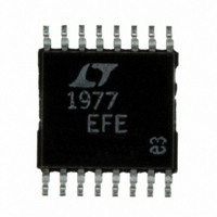
LT1977EFE#PBF Linear Technology, LT1977EFE#PBF Datasheet - Page 23

LT1977EFE#PBF
Manufacturer Part Number
LT1977EFE#PBF
Description
IC REG SW 1.5A HV STP DN 16TSSOP
Manufacturer
Linear Technology
Type
Step-Down (Buck)r
Datasheet
1.LT1977EFEPBF.pdf
(24 pages)
Specifications of LT1977EFE#PBF
Internal Switch(s)
Yes
Synchronous Rectifier
No
Number Of Outputs
1
Voltage - Output
1.2 ~ 54 V
Current - Output
1.5A
Frequency - Switching
500kHz
Voltage - Input
3.3 ~ 60 V
Operating Temperature
-40°C ~ 125°C
Mounting Type
Surface Mount
Package / Case
16-TSSOP Exposed Pad, 16-eTSSOP, 16-HTSSOP
Primary Input Voltage
60V
No. Of Outputs
1
Output Voltage
54V
Output Current
3.5A
No. Of Pins
16
Operating Temperature Range
-40°C To +125°C
Msl
MSL 1 - Unlimited
Rohs Compliant
Yes
Dc To Dc Converter Type
Step Down
Pin Count
16
Input Voltage
60V
Switching Freq
575KHz
Package Type
TSSOP EP
Output Type
Adjustable
Switching Regulator
Yes
Mounting
Surface Mount
Input Voltage (min)
2.4V
Operating Temp Range
-40C to 125C
Operating Temperature Classification
Automotive
Lead Free Status / RoHS Status
Lead free / RoHS Compliant
Power - Output
-
Lead Free Status / Rohs Status
Compliant
Available stocks
Company
Part Number
Manufacturer
Quantity
Price
APPLICATIO S I FOR ATIO
First, the combination of output capacitor ESR and a large
R
loop gain is not rolled off sufficiently at the switching fre-
quency output ripple will perturb the V
unstable duty cycle switching similar to subharmonic
oscillation. This may not be apparent at the output. Small-
signal analysis will not show this since a continuous time
PACKAGE DESCRIPTIO
C
may stop loop gain rolling off altogether. Second, if the
6.60 ±0.10
U
NOTE:
1. CONTROLLING DIMENSION: MILLIMETERS
2. DIMENSIONS ARE IN
3. DRAWING NOT TO SCALE
(.0035 – .0079)
0.09 – 0.20
4.50 ±0.10
RECOMMENDED SOLDER PAD LAYOUT
U
Information furnished by Linear Technology Corporation is believed to be accurate and reliable.
However, no responsibility is assumed for its use. Linear Technology Corporation makes no represen-
tation that the interconnection of its circuits as described herein will not infringe on existing patent rights.
(.169 – .177)
SEE NOTE 4
4.30 – 4.50*
(.020 – .030)
W
(.141)
0.50 – 0.75
MILLIMETERS
3.58
0.65 BSC
C
(INCHES)
U
pin enough to cause
0.45 ±0.05
16-Lead Plastic TSSOP (4.4mm)
(.116)
(Reference LTC DWG # 05-08-1663)
2.94
1.05 ±0.10
U
Exposed Pad Variation BC
0.25
REF
*DIMENSIONS DO NOT INCLUDE MOLD FLASH. MOLD FLASH
4. RECOMMENDED MINIMUM PCB METAL SIZE
SHALL NOT EXCEED 0.150mm (.006") PER SIDE
FOR EXPOSED PAD ATTACHMENT
0° – 8°
FE Package
system is assumed. If needed, an additional capacitor (C
can be added to form a pole at below the switching frequency
(if R
When checking loop stability the circuit should be oper-
ated over the application’s full voltage, current and tem-
perature range. Any transient loads should be applied and
the output voltage monitored for a well-damped behavior.
C
(.0256)
0.65
BSC
= 26k, C
16 1514 13 12 11
1
(.0077 – .0118)
0.195 – 0.30
2
TYP
C
(.193 – .201)
3 4 5 6 7 8
4.90 – 5.10*
= 1500pF, C
(.141)
3.58
10
9
(.002 – .006)
0.05 – 0.15
FE16 (BC) TSSOP 0204
F
= 330pF).
(.0433)
(.116)
2.94
MAX
1.10
(.252)
6.40
BSC
LT1977
23
1977fa
F
)


