LT1070HVCT#PBF Linear Technology, LT1070HVCT#PBF Datasheet - Page 6

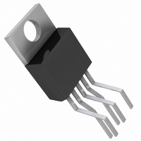
LT1070HVCT#PBF
Manufacturer Part Number
LT1070HVCT#PBF
Description
IC SWITCH REG 5A HI-EFF TO220-5
Manufacturer
Linear Technology
Type
Step-Down (Buck), Step-Up (Boost), Inverting, Cuk, Flyback, Forward Converterr
Datasheet
1.LT1071CTPBF.pdf
(12 pages)
Specifications of LT1070HVCT#PBF
Internal Switch(s)
Yes
Synchronous Rectifier
No
Number Of Outputs
1
Voltage - Output
1.25 ~ 60 V
Current - Output
5A
Frequency - Switching
40kHz
Voltage - Input
3 ~ 60 V
Operating Temperature
0°C ~ 100°C
Mounting Type
Through Hole
Package / Case
TO-220-5 (Bent and Staggered Leads)
Power - Output
100W
Lead Free Status / RoHS Status
Lead free by exemption / RoHS Compliant
Available stocks
Company
Part Number
Manufacturer
Quantity
Price
LT1070/LT1071
TYPICAL PERFORMANCE CHARACTERISTICS
BLOCK
OPERATION
The LT1070/LT1071 is a current mode switcher. This
means that switch duty cycle is directly controlled by
switch current rather than by output voltage. Referring to
the Block Diagram, the switch is turned “on” at the start
of each oscillator cycle. It is turned “off” when switch
current reaches a predetermined level. Control of output
6
1000
900
800
700
600
500
400
300
200
100
0
Switch “Off” Characteristics
0
V
SUPPLY
10
20
3V
=
DIAGRAM
SWITCH VOLTAGE (V)
30
15V
40
V
U
IN
FB
50
SELECT
40kHz
MODE
40V
60
1.24V
2.3V
REG
OSC
REF
70
W
55V
W
80
1070/71 G19
–
+
90
ERROR
AMP
U
100
–100
– 400
– 200
– 300
300
200
100
0
0
V
T
C
J
= 25 C
Pin Characteristics
0.5
(CURRENT OUT OF V
SHUTDOWN
CIRCUIT
V
(CURRENT INTO
V
V
FB
C
C
PIN)
PIN VOLTAGE (V)
V
= 1.5V
1.0
FB
= 0.8V
1.5
voltage is obtained by using the output of a voltage
sensing error amplifier to set current trip level. This
technique has several advantages. First, it has immediate
response to input voltage variations, unlike ordinary
switchers which have notoriously poor line transient
response. Second, it reduces the 90 phase shift at
LOGIC
COMP
0.15V
C
V
C
PIN)
2.0
1070/71 G20
FLYBACK
ERROR
AMP
GAIN 6
2.5
CURRENT
ANTISAT
DRIVER
–1000
AMP
7000
6000
5000
4000
3000
2000
1000
0
+
–
1k
16V
Transconductance of Error
Amplifier
10k
5A, 75V
SWITCH
0.02
(0.04 LT1071)
1070/71 BD
FREQUENCY (Hz)
SWITCH
OUT
100k
g
m
1M
1070/71 G21
10M
10701fe
– 30
0
30
60
90
120
150
180
210


