LT1070HVCT#PBF Linear Technology, LT1070HVCT#PBF Datasheet - Page 7
LT1070HVCT#PBF
Manufacturer Part Number
LT1070HVCT#PBF
Description
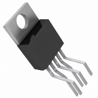
IC SWITCH REG 5A HI-EFF TO220-5
Manufacturer
Linear Technology
Type
Step-Down (Buck), Step-Up (Boost), Inverting, Cuk, Flyback, Forward Converterr
Datasheet
1.LT1071CTPBF.pdf
(12 pages)
Specifications of LT1070HVCT#PBF
Internal Switch(s)
Yes
Synchronous Rectifier
No
Number Of Outputs
1
Voltage - Output
1.25 ~ 60 V
Current - Output
5A
Frequency - Switching
40kHz
Voltage - Input
3 ~ 60 V
Operating Temperature
0°C ~ 100°C
Mounting Type
Through Hole
Package / Case
TO-220-5 (Bent and Staggered Leads)
Power - Output
100W
Lead Free Status / RoHS Status
Lead free by exemption / RoHS Compliant
Available stocks
Company
Part Number
Manufacturer
Quantity
Price


OPERATION
midfrequencies in the energy storage inductor. This
greatly simplifies closed-loop frequency compensation
under widely varying input voltage or output load condi-
tions. Finally, it allows simple pulse-by-pulse current
limiting to provide maximum switch protection under
output overload or short-circuit conditions. A low drop-
out internal regulator provides a 2.3V supply for all
internal circuitry of the LT1070/LT1071. This low drop-
out design allows input voltage to vary from 3V to 60V
with virtually no change in device performance. A 40kHz
oscillator is the basic clock for all internal timing. It turns
“on” the output switch via the logic and driver circuitry.
Special adaptive antisat circuitry detects onset of satura-
tion in the power switch and adjusts driver current
instantaneously to limit switch saturation. This mini-
mizes driver dissipation and provides very rapid turn-off
of the switch.
A 1.2V bandgap reference biases the positive input of the
error amplifier. The negative input is brought out for
output voltage sensing. This feedback pin has a second
function; when pulled low with an external resistor, it
programs the LT1070/LT1071 to disconnect the main
error amplifier output and connects the output of the
flyback amplifier to the comparator input. The LT1070/
LT1071 will then regulate the value of the flyback pulse
with respect to the supply voltage. This flyback pulse is
directly proportional to output voltage in the traditional
TYPICAL APPLICATIONS
10V
20V
TO
Driving High Voltage FET (for Off-Line
+
U
Applications, See AN25)
LT1070/LT1071
GND
V
IN
1070/71 TA03
1 0 7 0 / 7 1
V
SW
T A 0 3
U
D1
G
(Note that maximum output currents are divided by 2 for the LT1071)
D
S
Q1
transformer coupled flyback topology regulator. By regu-
lating the amplitude of the flyback pulse, the output
voltage can be regulated with no direct connection be-
tween input and output. The output is fully floating up to
the breakdown voltage of the transformer windings.
Multiple floating outputs are easily obtained with addi-
tional windings. A special delay network inside the LT1070/
LT1071 ignores the leakage inductance spike at the
leading edge of the flyback pulse to improve output
regulation.
The error signal developed at the comparator input is
brought out externally. This pin (V
functions. It is used for frequency compensation, current
limit adjustment, soft starting and total regulator shut-
down. During normal regulator operation this pin sits at
a voltage between 0.9V (low output current) and 2.0V
(high output current). The error amplifiers are current
output (g
clamped for adjusting current limit. Likewise, a capacitor
coupled external clamp will provide soft start. Switch
duty cycle goes to zero if the V
through a diode, placing the LT1070/LT1071 in an idle
mode. Pulling the V
regulator shutdown, with only 50 A supply current for
shutdown circuitry biasing. See AN19 for full application
details.
m
) types, so this voltage can be externally
LT1070/LT1071
Driving High Voltage NPN
GND
V
IN
V
C
SW
pin below 0.15V causes total
R2**
D1
LT1070/LT1071
**
C
*
C1
D2
SETS I
SETS I
R1*
pin is pulled to ground
C
B(ON)
B(OFF)
) has four different
1070/71 TA16
Q1
10701fe
7
Related parts for LT1070HVCT#PBF
Image
Part Number
Description
Manufacturer
Datasheet
Request
R

Part Number:
Description:
5a And 2.5a High Efficiency Switching Regulators
Manufacturer:
Linear Technology Corporation
Datasheet:

Part Number:
Description:
CD ROM LINEARVIEW DATASHEETS
Manufacturer:
Linear Technology
Part Number:
Description:
Standalone Linear Li-Ion Battery Charger with Thermal Regulation in ThinSOT
Manufacturer:
Linear Technology Corporation
Datasheet:
Part Number:
Description:
Low noise, high frequency, 8th order linear phase lowpass filter
Manufacturer:
Linear Technology Corporation
Datasheet:
Part Number:
Description:
Manufacturer:
Linear Technology Corporation
Datasheet:
Part Number:
Description:
Manufacturer:
Linear Technology Corporation
Datasheet:
Part Number:
Description:
Manufacturer:
Linear Technology Corporation
Datasheet:
Part Number:
Description:
Manufacturer:
Linear Technology Corporation
Datasheet:
Part Number:
Description:
Manufacturer:
Linear Technology Corporation
Datasheet:
Part Number:
Description:
Manufacturer:
Linear Technology Corporation
Datasheet:
Part Number:
Description:
Manufacturer:
Linear Technology Corporation
Datasheet:
Part Number:
Description:
Dual and Quad, JFET Input Precision High Speed Op Amps
Manufacturer:
Linear Technology Corporation
Datasheet:
Part Number:
Description:
Manufacturer:
Linear Technology Corporation
Datasheet:
Part Number:
Description:
1, 2, 6 and 8 Channel, 10-Bit Serial I/O Data Acquisition Systems
Manufacturer:
Linear Technology Corporation
Datasheet:
Part Number:
Description:
Manufacturer:
Linear Technology Corporation
Datasheet: