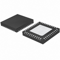
BD95500MUV-E2 Rohm Semiconductor, BD95500MUV-E2 Datasheet - Page 7

BD95500MUV-E2
Manufacturer Part Number
BD95500MUV-E2
Description
IC BUCK ADJ 6A 40VQFN
Manufacturer
Rohm Semiconductor
Type
Step-Down (Buck)r
Datasheet
1.BD95500MUV-E2.pdf
(20 pages)
Specifications of BD95500MUV-E2
Internal Switch(s)
Yes
Synchronous Rectifier
No
Number Of Outputs
1
Voltage - Output
0.7 ~ 5 V
Current - Output
6A
Frequency - Switching
30kHz ~ 100kHz
Voltage - Input
3 ~ 20 V
Operating Temperature
-10°C ~ 100°C
Mounting Type
Surface Mount
Package / Case
40-VQFN
Power - Output
4.66W
Output Voltage
7 V
Output Current
6 A
Input Voltage
3 V to 20 V
Switching Frequency
200 KHz to 1000 KHz
Operating Temperature Range
- 10 C to + 100 C
Mounting Style
SMD/SMT
Lead Free Status / RoHS Status
Lead free / RoHS Compliant
Other names
BD95500MUV-E2TR
MODE
BOOT
VINS
VIN
VIN
VIN
VIN
VIN
VIN
EN
●Block Diagram
●Pin Configuration
31
32
33
34
35
36
37
38
39
40
*Connect the bottom side (FIN) to the ground terminal
PGOOD N.C.
PGND
Vcc
30
1
PGOOD
V
REF
EN
OUT
SW
29
2
39
10
11
1
SW
28
CE
3
REF×0.85
Protection
SS×0.85
Thermal
Reference
VDD
Block
V
SW
ILIM
27
OUT
4
5
Power
Good
EN/UVLO
Vcc
VCC GND VREG
SW
26
5
6
TSD
GND
SS
SW
25
Delay
6
VREG
UVLO
SCP
TSD
ILIM
VIN
SW
24
7
SCP
8
SW
VIN
UVLO
23
FS
Controller
8
H
FS
3
Block
Reg
37
TRACK
SW
22
VINS
TM
9
SS/
40
2.5VReg
MODE
PGND
REF
21
10
2
REF×1.2
7
N.C.
R
S
20
19
18
17
16
15
14
13
12
11
VREG
V
2.5V
OUT
PGND
PGND
PGND
PGND
PGND
PGND
VDD
VOUT
Q
Is-
Is+
4
ILIM
7/20
ILIM
×0.1
●Pin Function Table
Current Limit
SLLM/
OVP
MODE
bottom
9
15-21
22-29
31-36
SS
PIN
No.
10
12
13
14
30
37
38
39
40
13
11
1
2
3
4
5
6
7
8
9
Is+
Soft Start
12
Is-
SS
Circuit
PIN name
Driver
PGOOD
TRACK
PGND
MODE
VREG
VOUT
PGND
BOOT
VINS
GND
N.C.
VCC
REF
VDD
ILIM
SS/
SW
VIN
FIN
CE
Is+
EN
FS
Is-
VDD
Power Good Output Pin
-
Ceramic Capacitor Reactive Pin
Current Limit Setting Pin
Power Supply Input pin (Control Block)
Sense GND
IC Reference Voltage (2.5V/500uA)
Switching Frequency Adjustable Pin
Soft Start Setting Pin (w/ Capacitor)/
Tracking Voltage Input Pin
Vo Setting Pin
Output Voltage Sense Pin
Current Sense Pin -
Current Sense Pin +
FET Driver Power Supply Pin (5V Input)
Power GND Pin
High Side FET Source Pin
Power GND Pin
Battery Voltage Input pin
Battery Voltage Sense pin
HG Driver Power Supply Pin
Enable Input pin (IC ON when High)
Control Mode Adjustment Pin
Substrate connection
(+/-10% Window)
Low: Continuous
High: SLLM
(30k∼100kΩ)
(3.3~20V Input)
31
36
14
15
21
30
38
22
29
3
|
|
|
VDD
CE
PGND
BOOT
VIN
PGND
SW
PIN function
5V
C
IN
3.3V∼
20V
V
C
OUT
OUT


