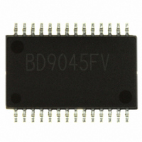
BD9045FV-E2 Rohm Semiconductor, BD9045FV-E2 Datasheet - Page 9

BD9045FV-E2
Manufacturer Part Number
BD9045FV-E2
Description
IC REG SW STEP DOWN HE 28SSOP
Manufacturer
Rohm Semiconductor
Type
Step-Down (Buck)r
Datasheet
1.BD9040FV-E2.pdf
(17 pages)
Specifications of BD9045FV-E2
Internal Switch(s)
No
Synchronous Rectifier
Yes
Number Of Outputs
2
Frequency - Switching
200kHz ~ 750kHz
Voltage - Input
4.5 ~ 18 V
Mounting Type
Surface Mount
Package / Case
28-SSOP
Power - Output
940mW
Primary Input Voltage
12V
No. Of Outputs
1
Output Voltage
5.5V
Output Current
6mA
Voltage Regulator Case Style
SSOP
No. Of Pins
28
Operating Temperature Range
-40°C To +85°C
Svhc
No SVHC
Lead Free Status / RoHS Status
Lead free / RoHS Compliant
Current - Output
-
Voltage - Output
-
Operating Temperature
-
Lead Free Status / Rohs Status
Lead free / RoHS Compliant
Other names
BD9045FV-E2TR
Available stocks
Company
Part Number
Manufacturer
Quantity
Price
Company:
Part Number:
BD9045FV-E2
Manufacturer:
ROHM
Quantity:
2 448
(6) Setting of soft start time
following formula.
(8) Overcurrent protection
(5) Setting of oscillating frequency
(4) Design of feedback resistance constant
(7) Setting of EN_SS (output delay function)(in the case of BD9040FV)
Please refer to the following formula for design of feedback resistance. The 1kΩ~330kΩ is recommended as its setting range. If it is no more
The soft start is necessary for preventing the excessive increase of coil current at the time of start-up and the overshoot at the time of start-up of
If the capacitance value is reduced (to no more than 0.01 uF or so), the overshoot in output may be caused.
If there is a start-up relation (sequence) with other power supplies, please use high-accuracy parts (x5R) etc.
than 1kΩ, drop in electric power efficiency will be caused. Moreover, if more than 330kΩ is set, the offset voltage becomes large due to the
internal error amplifier’s input bias current of 0.4uA.
The current limit is self-feedback type, when overcurrent is detected, the output Duty is reduced, and the current is limited. When load returns to
Triangular wave oscillating frequency can be set by connecting a resistor to RT pin. RT determines the currents of charging & discharging the
internal capacitor, and the frequency changes. Please refer to the following diagram for setting of the resistance of RT.
If setting is off the range of the following diagram, the switching may stop, and so normal operation can not be ensured, therefore please be
careful.
Still more, the soft start time & waveform vary with input voltage, output voltage, load, coil, output capacitance and phase
compensation constant etc, so please confirm with actual devices.
Current limit value (ILimit) is determined by the resistance RCL connected between VCC and CL. (refer to the following diagram)
output voltage. The calculating formula for capacitor & soft start time is shown in the formula (8).
If EN_SS is made to be L, the output voltage’s OFF time can be made delayed. The calculating formula for delay time is shown in the
T
SL
= 0.8 ×
TDIS=
Iss(10uA typ)
Vss_MAX(1.95VTyp)-(0.8+0.7×
Vo
R1
R2
Css
750
700
650
600
550
500
450
400
350
300
250
200
0
VO
VCC
EN_SS
FB
[sec]
Internal reference
20
T
40
SL
0.9V
T
T
SH
SH
60
= 0.7 ×
Vcc
Vo
R T [ kΩ]
9/16
) ×
80
Idis(3.3uA,Typ)
Vcc
Vo
100
Vo =
Css
×
Tdis
R1 +R2
120
R2
Iss(10uA typ)
[sec]・・・(9)
140
Css
× 0.9 [V] ・・・ (7)
160
[sec]・・・ (8)


