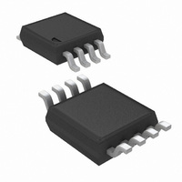
LM3485MM/NOPB National Semiconductor, LM3485MM/NOPB Datasheet - Page 10

LM3485MM/NOPB
Manufacturer Part Number
LM3485MM/NOPB
Description
IC CONTROLLER PFET 8-MSOP
Manufacturer
National Semiconductor
Type
Step-Down (Buck)r
Datasheet
1.LM3485MMNOPB.pdf
(16 pages)
Specifications of LM3485MM/NOPB
Internal Switch(s)
No
Synchronous Rectifier
No
Number Of Outputs
1
Voltage - Output
1.24 ~ 35 V
Current - Output
4A
Voltage - Input
4.5 ~ 35 V
Operating Temperature
-40°C ~ 125°C
Mounting Type
Surface Mount
Package / Case
8-MSOP, Micro8™, 8-uMAX, 8-uSOP,
Power - Output
417mW
Dc To Dc Converter Type
Buck Controller
Pin Count
8
Input Voltage
4.5 to 35V
Output Voltage
1.242 to 35V
Output Current
4A
Package Type
MSOP
Mounting
Surface Mount
Operating Temperature Classification
Automotive
Operating Temperature (min)
-40C
Operating Temperature (max)
125C
For Use With
LM3485LED EVAL - BOARD EVALUATION LM3485LEDLM3485EVAL - BOARD EVALUATION LM3485
Lead Free Status / RoHS Status
Lead free / RoHS Compliant
Frequency - Switching
-
Lead Free Status / Rohs Status
Compliant
Other names
LM3485MM
LM3485MMTR
LM3485MMTR
Available stocks
Company
Part Number
Manufacturer
Quantity
Price
Company:
Part Number:
LM3485MM/NOPB
Manufacturer:
TI
Quantity:
5 600
Part Number:
LM3485MM/NOPB
Manufacturer:
NS/国半
Quantity:
20 000
www.national.com
will not be accidentally triggered. A value of 100pF to 1nF is
recommended in most applications. Higher values can be
used to create a soft-start function (See Start Up section).
The current limit comparator has approximately 100ns of
blanking time. This ensures that the PFET is fully on when the
current is sensed. However, under extreme conditions such
as cold temperature, some PFETs may not fully turn on within
the blanking time. In this case, the current limit threshold must
be increased. If the current limit function is used, the on time
must be greater than 100ns. Under low duty cycle operation,
the maximum operating frequency will be limited by this min-
imum on time.
During current limit operation, the output voltage will drop sig-
nificantly as will operating frequency. As the load current is
reduced, the output will return to the programmed voltage.
However, there is a current limit fold back phenomenon in-
herent in this current limit architecture. See
At high input voltages (>28V) increased undershoot at the
switch node can cause an increase in the current limit thresh-
old. To avoid this problem, a low Vf Schottky catch diode must
be used (See Catch Diode Selection). Additionally, a resistor
can be placed between the ISENSE pin and the switch node.
Any value up to approximately 600Ω is recommended.
START UP
The current limit circuit is active during start-up. During start-
up the PFET will stay on until either the current limit or the
feedback comparator is tripped
If the current limit comparator is tripped first then the fold back
characteristic should be taken into account. Start-up into full
load may require a higher current limit set point or the load
must be applied after start-up.
One problem with selecting a higher current limit is inrush
current during start-up. Increasing the capacitance (C
parallel with R
FIGURE 4. Current Limit Fold Back Phenomenon
ADJ
results in soft-start. C
20034626
ADJ
Figure
and R
ADJ
4.
ADJ
create
) in
10
an RC time constant forcing current limit to activate at a lower
current. The output voltage will ramp more slowly when using
the soft-start functionality. There are example start-up plots
for C
Characteristics. Lower values for C
effect on soft-start.
EXTERNAL SENSE RESISTOR
The V
ature. This will result an equivalent variation in current limit.
To improve current limit accuracy an external sense resistor
can be connected from V
shown in
PGATE
When switching, the PGATE pin swings from VIN (off) to
some voltage below VIN (on). How far the PGATE will swing
depends on several factors including the capacitance, on
time, and input voltage.
As shown in the Typical Performance Characteristics,
PGATE voltage swing will increase with decreasing gate ca-
pacitance. Although PGATE voltage will typically be around
VIN-5V, with every small gate capacitances, this value can
increase to a typical maximum of VIN-8.3V.
Additionally, PGATE swing voltage will increase as on time
increases. During long on times, such as when operating at
100% duty cycle, the PGATE voltage will eventually fall to its
maximum voltage of VIN-8.3V (typical) regardless of the
PFET gate capacitance.
The PGATE voltage will not fall below 0.4V (typical). There-
fore, when the input voltage falls below approximately 9V, the
PGATE swing voltage range will be reduced. At an input volt-
age of 7V, for instance, PGATE will swing from 7V to a
minimum of 0.4V.
FIGURE 5. Current Sensing by External Resistor
ADJ
DS
of a PFET will tend to vary significantly over temper-
equal to 1nF and 10nF in the Typical Performance
Figure
5.
IN
to the source of the PFET, as
ADJ
will have little to no
20034627


