ICL7660SCBA Intersil, ICL7660SCBA Datasheet - Page 11
ICL7660SCBA
Manufacturer Part Number
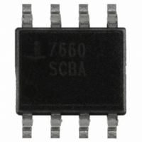
ICL7660SCBA
Description
IC MULTI CONFIG 8SOIC
Manufacturer
Intersil
Type
Switched Capacitor (Charge Pump), Doubler, Invertingr
Datasheet
1.ICL7660SIBAZT.pdf
(12 pages)
Specifications of ICL7660SCBA
Internal Switch(s)
Yes
Synchronous Rectifier
No
Number Of Outputs
1
Frequency - Switching
10kHz, 35kHz
Voltage - Input
1.5 ~ 12 V
Operating Temperature
0°C ~ 70°C
Mounting Type
Surface Mount
Package / Case
8-SOIC (3.9mm Width)
Lead Free Status / RoHS Status
Contains lead / RoHS non-compliant
Current - Output
-
Voltage - Output
-
Power - Output
-
Available stocks
Company
Part Number
Manufacturer
Quantity
Price
Company:

Part Number:
ICL7660SCBA
Manufacturer:
MAXIM
Quantity:
1
Part Number:
ICL7660SCBA
Manufacturer:
HAR
Quantity:
20 000
Part Number:
ICL7660SCBA-T
Manufacturer:
INTERSIL
Quantity:
20 000
Company:
Part Number:
ICL7660SCBAZ
Manufacturer:
Intersil
Quantity:
14 977
Part Number:
ICL7660SCBAZ
Manufacturer:
INT
Quantity:
20 000
Company:
Part Number:
ICL7660SCBAZ-T
Manufacturer:
Intersil
Quantity:
20 000
Part Number:
ICL7660SCBAZ-T
Manufacturer:
INTERSIL
Quantity:
20 000


SEATING
Dual-In-Line Plastic Packages (PDIP)
INDEX
NOTES:
10. Corner leads (1, N, N/2 and N/2 + 1) for E8.3, E16.3, E18.3,
AREA
1. Controlling Dimensions: INCH. In case of conflict between
2. Dimensioning and tolerancing per ANSI Y14.5M-1982.
3. Symbols are defined in the “MO Series Symbol List” in Section
4. Dimensions A, A1 and L are measured with the package seated
5. D, D1, and E1 dimensions do not include mold flash or protru-
6. E and
7. e
8. B1 maximum dimensions do not include dambar protrusions.
9. N is the maximum number of terminal positions.
PLANE
PLANE
BASE
English and Metric dimensions, the inch dimensions control.
2.2 of Publication No. 95.
in JEDEC seating plane gauge GS-3.
sions. Mold flash or protrusions shall not exceed 0.010 inch
(0.25mm).
pendicular to datum
strained. e
Dambar protrusions shall not exceed 0.010 inch (0.25mm).
E28.3, E42.6 will have a B1 dimension of 0.030 - 0.045 inch
(0.76 - 1.14mm).
D1
B1
B
and e
-A-
N
e
1 2 3
C
B
A
C
are measured at the lead tips with the leads uncon-
are measured with the leads constrained to be per-
must be zero or greater.
D
0.010 (0.25)
-C-
e
.
N/2
11
D1
M
-C-
E1
C A
-B-
A
1
A2
B S
L
e
A
C
e
e
C L
E
A
C
B
ICL7660S
E8.3
8 LEAD DUAL-IN-LINE PLASTIC PACKAGE
SYMBOL
A1
A2
B1
D1
E1
e
e
C
D
N
A
B
E
e
L
A
B
(JEDEC MS-001-BA ISSUE D)
0.015
0.115
0.014
0.045
0.008
0.355
0.005
0.300
0.240
0.115
MIN
-
-
0.100 BSC
0.300 BSC
INCHES
8
MAX
0.210
0.195
0.022
0.070
0.014
0.400
0.325
0.280
0.430
0.150
-
-
MILLIMETERS
0.39
2.93
0.356
1.15
0.204
9.01
0.13
7.62
6.10
2.93
MIN
-
-
2.54 BSC
7.62 BSC
8
10.16
10.92
MAX
5.33
4.95
0.558
1.77
0.355
8.25
7.11
3.81
-
-
Rev. 0 12/93
March 6, 2008
NOTES
FN3179.5
8, 10
4
4
5
5
6
5
6
7
4
9
-
-
-
-
Related parts for ICL7660SCBA
Image
Part Number
Description
Manufacturer
Datasheet
Request
R

Part Number:
Description:
CMOS Voltage Converters
Manufacturer:
Intersil Corporation
Datasheet:
Part Number:
Description:
Intersil Corporation [CMOS Serial Controller Interface]
Manufacturer:
Intersil Corporation
Datasheet:
Part Number:
Description:
Manufacturer:
Intersil Corporation
Datasheet:
Part Number:
Description:
357-036-542-201 CARDEDGE 36POS DL .156 BLK LOPRO
Manufacturer:
Intersil Corporation
Datasheet:
Part Number:
Description:
1024-Word x 4-Bit LSI Static RAM
Manufacturer:
Intersil Corporation
Datasheet:
Part Number:
Description:
General Purpose NPN Transistor Arrays FN341.4
Manufacturer:
Intersil Corporation
Datasheet:
Part Number:
Description:
CMOS 16-Bit Microprocessor
Manufacturer:
Intersil Corporation
Datasheet:
Part Number:
Description:
Manufacturer:
Intersil Corporation
Datasheet:
Part Number:
Description:
Manufacturer:
Intersil Corporation
Datasheet:
Part Number:
Description:
Manufacturer:
Intersil Corporation
Datasheet:
Part Number:
Description:
Manufacturer:
Intersil Corporation
Datasheet:
Part Number:
Description:
CMOS 6-Bit Latch and Decoder Memory Interfaces
Manufacturer:
Intersil Corporation
Datasheet:
Part Number:
Description:
CA3046General Purpose NPN Transistor Arrays
Manufacturer:
Intersil Corporation
Datasheet:
Part Number:
Description:
Manufacturer:
Intersil Corporation
Datasheet:
Part Number:
Description:
TR909 DLC/FLC SLIC with Low Power Standby
Manufacturer:
Intersil Corporation
Datasheet: