LM2592HVT-ADJ/NOPB National Semiconductor, LM2592HVT-ADJ/NOPB Datasheet - Page 17
LM2592HVT-ADJ/NOPB
Manufacturer Part Number
LM2592HVT-ADJ/NOPB
Description
IC REG SIMPLE SWITCHER TO220-5
Manufacturer
National Semiconductor
Series
SIMPLE SWITCHER®r
Type
Step-Down (Buck)r
Datasheet
1.LM2592HVS-ADJNOPB.pdf
(20 pages)
Specifications of LM2592HVT-ADJ/NOPB
Internal Switch(s)
Yes
Synchronous Rectifier
No
Number Of Outputs
1
Voltage - Output
1.2 ~ 57 V
Current - Output
2A
Frequency - Switching
150kHz
Voltage - Input
4.5 ~ 60 V
Operating Temperature
-40°C ~ 125°C
Mounting Type
Through Hole
Package / Case
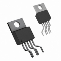
TO-220-5 (Bent and Staggered Leads)
Primary Input Voltage
60V
No. Of Outputs
1
Output Voltage
57V
Output Current
2A
No. Of Pins
5
Operating Temperature Range
-40°C To +125°C
Filter Terminals
Through Hole
Rohs Compliant
Yes
Lead Free Status / RoHS Status
Lead free / RoHS Compliant
Power - Output
-
Other names
*LM2592HVT-ADJ
*LM2592HVT-ADJ/NOPB
LM2592HVT-ADJ
*LM2592HVT-ADJ/NOPB
LM2592HVT-ADJ


Application Information
Because of differences in the operation of the inverting
regulator, the standard design procedure is not used to
select the inductor value. In the majority of designs, a 33 µH,
4A inductor is the best choice. Capacitor selection can also
be narrowed down to just a few values.
This type of inverting regulator can require relatively large
amounts of input current when starting up, even with light
loads. Input currents as high as the LM2592HV current limit
(approx 4A) are needed for at least 2 ms or more, until the
output reaches its nominal output voltage. The actual time
depends on the output voltage and the size of the output
capacitor. Input power sources that are current limited or
sources that can not deliver these currents without getting
loaded down, may not work correctly. Because of the rela-
tively high startup currents required by the inverting topology,
THERMAL CONSIDERATIONS
The LM2592HV is available in two packages, a 5-pin TO-220
(T) and a 5-pin surface mount TO-263 (S).
The TO-220 package needs a heat sink under most condi-
tions. The size of the heatsink depends on the input voltage,
the output voltage, the load current and the ambient tem-
perature. Higher ambient temperatures require more heat
sinking.
The TO-263 surface mount package tab is designed to be
soldered to the copper on a printed circuit board. The copper
and the board are the heat sink for this package and the
other heat producing components, such as the catch diode
and inductor. The PC board copper area that the package is
FIGURE 13. Inverting Regulator Ground Referenced Shutdown using Opto Device
FIGURE 12. Inverting Regulator Ground Referenced Shutdown
(Continued)
17
the delayed startup feature (C1, R
11 is recommended. By delaying the regulator startup, the
input capacitor is allowed to charge up to a higher voltage
before the switcher begins operating. A portion of the high
input current needed for startup is now supplied by the input
capacitor (C
capacitor can be made much larger than normal.
lNVERTING REGULATOR SHUTDOWN METHODS
To use the ON /OFF pin in a standard buck configuration is
simple, pull it below 1.3V (
turn regulator ON, pull it above 1.3V to shut the regulator
OFF. With the inverting configuration, some level shifting is
required, because the ground pin of the regulator is no
longer at ground, but is now setting at the negative output
voltage level. Two different shutdown methods for inverting
regulators are shown in Figure 12 and Figure 13
soldered to should be at least 0.4 in
have 2 or more square inches of 2 oz. (0.0028) in) copper.
Additional copper area improves the thermal characteristics,
but with copper areas greater than approximately 6 in
small improvements in heat dissipation are realized. If fur-
ther thermal improvements are needed, double sided, mul-
tilayer PC board with large copper areas and/or airflow are
recommended.
The curves shown in Figure 14 show the LM2592HVS
(TO-263 package) junction temperature rise above ambient
temperature with a 2A load for various input and output
voltages. This data was taken with the circuit operating as a
buck switching regulator with all components mounted on a
IN
). For severe start up conditions, the input
10129442
10129486
@
25˚C, referenced to ground) to
1
and R
2
, and ideally should
2
) shown in Figure
www.national.com
2
, only
Related parts for LM2592HVT-ADJ/NOPB
Image
Part Number
Description
Manufacturer
Datasheet
Request
R

Part Number:
Description:
IC REG SIMPLE SWITCHER TO220-5
Manufacturer:
National Semiconductor
Datasheet:

Part Number:
Description:
SWITCHING REG 2A 3.3V, 2592, TO-220
Manufacturer:
National Semiconductor
Datasheet:

Part Number:
Description:
Voltage Regulator IC
Manufacturer:
National Semiconductor
Datasheet:
Part Number:
Description:
Voltage Regulator IC
Manufacturer:
National Semiconductor
Datasheet:
Part Number:
Description:
IC REG SIMPLE SWITCHER TO220-5
Manufacturer:
National Semiconductor
Datasheet:

Part Number:
Description:
National Semiconductor [8-Bit D/A Converter]
Manufacturer:
National Semiconductor
Datasheet:
Part Number:
Description:
National Semiconductor [Media Coprocessor]
Manufacturer:
National Semiconductor
Datasheet:
Part Number:
Description:
Digitally Controlled Tone and Volume Circuit with Stereo Audio Power Amplifier, Microphone Preamp Stage and National 3D Sound
Manufacturer:
National Semiconductor
Datasheet:
Part Number:
Description:
Digitally Controlled Tone and Volume Circuit with Stereo Audio Power Amplifier, Microphone Preamp Stage and National 3D Sound
Manufacturer:
National Semiconductor
Datasheet:
Part Number:
Description:
AC97 Rev 2 Codec with Sample Rate Conversion and National 3D Sound
Manufacturer:
National Semiconductor
Part Number:
Description:
Manufacturer:
National Semiconductor
Datasheet:
Part Number:
Description:
Manufacturer:
National Semiconductor
Datasheet:
Part Number:
Description:
General Purpose, Low Voltage, Low Power, Rail-to-Rail Output Operational Amplifiers
Manufacturer:
National Semiconductor
Datasheet: