LM3207TL/NOPB National Semiconductor, LM3207TL/NOPB Datasheet
LM3207TL/NOPB
Specifications of LM3207TL/NOPB


Related parts for LM3207TL/NOPB


LM3207TL/NOPB Summary of contents
Page 1
... High switching frequency (2MHz) allows use of surface- mount components. Only four small external surface-mount components are required, an inductor and three ceramic ca- pacitors. Typical Application © 2007 National Semiconductor Corporation Features ■ 2MHz (typ.) PWM Switching Frequency ■ Operates from a single Li-Ion cell (2.7V to 5.5V) ■ ...
Page 2
Connection Diagrams Order Information LDO Voltage Option Order Number 2.875 LM3207TL LM3207TLX 2.53 LM3207TL-2.53 LM3207TLX-2.53 Note: The actual physical placement of the package marking will vary from part to part. The package marking “X” designates the date code. “V” is ...
Page 3
... Absolute Maximum Ratings If Military/Aerospace specified devices are required, please contact the National Semiconductor Sales Office/ Distributors for availability and specifications SGND IN PGND to SGND EN, FB LDO CON LDO Continuous Power Dissipation (Note 3) Junction Temperature (T ) J-MAX Electrical Characteristics boldface type apply over the full operating ambient temperature range (−30°C ...
Page 4
Symbol Parameter Gain Gain CON OUT I V pin leakage current CON CON www.national.com Conditions ≤ ≤ 0.32V V 1.44V CON V = 1.0V CON 4 Min Typ Max Units 2.5 V/V µA ±1 ...
Page 5
System Characteristics values in the typical application circuit are used (L = 3.0µH, (DCR = 0.12Ω, FDK MIPW3226D3R0M 10µF, (6.3V, 0805, TDK C2012X5R0J106K 0402, TDK C1005X5R1A104KT) (or 220nF, (6.3V, 0402, TDK C1005X5R0J224KT))) . These parameters are ...
Page 6
Note 4: In applications where high power dissipation and/or poor package thermal resistance is present, the maximum ambient temperature may have to be de- rated. Maximum ambient temperature (T A-MAX of the device in the application (P ), and the ...
Page 7
LDO Short Circuit Current vs Voltage (V = 3.0V 100nF) IN LDO 20165360 LDO Power Supply Rejection Ratio (V = Vout + 0.5V 100nF) IN (nom) LDO 20165381 LDO Turn Off Time ...
Page 8
LDO Load Transient Repsonse (V = 3.2V 0.8V OUT www.national.com = 100nF) LDO 20165376 8 LDO V Out vs Temperature LDO (V = 3.6V,C = 100nF) IN LDO 20165377 ...
Page 9
LDO Typical Performance Curves (2.53 Option) LDO Voltage vs Load Current (C = 100nF) LDO LDO Short Circuit Current vs Voltage (V = 3.0V 100nF) IN LDO LDO Turn On Time 100nF) LDO LDO ...
Page 10
LDO V Out vs Temperature LDO (V = 3.6V,C IN LDO www.national.com = 100nF) 20165359 10 ...
Page 11
SWITCHER Typical Performance Curves Quiescent Current vs Supply Voltage ( 0V, No Switching, LDO Disabled) CON Shutdown Current vs Temperature ( 0V) CON Output Voltage Regulation(%) vs Output Load (V = 1.5V) ...
Page 12
Output Voltage vs Temperature (V = 3.6V OUT V Voltage vs Output Voltage CON (V = 4.2V LOAD Efficiency vs Output Current (V = 0.8V) OUT www.national.com Open/Closed Loop Current Limit vs Temperature = 3.4V) 20165318 ...
Page 13
Load Transient Response (V = 0.8V) OUT Startup (V = 3.6V 1.3V 1kΩ) IN OUT LOAD Shutdown Response = 10Ω 4.2V 3.4V OUT LOAD Load Transient Response (V = 4.2V, ...
Page 14
V Voltage Response CON (V = 4.2V 0.32V/1.44V CON Timed Current Limit Response (V = 3.6V) IN Output Voltage Ripple (V = 3.4V) OUT www.national.com = 10Ω 4.2V, V LOAD IN 20165308 20165310 Output ...
Page 15
R vs Temperature (microSMD) DSON (P-ch 200mA) SW 20165311 EN High Threshold 20165313 R vs Temperature (microSMD) DSON (N-ch -200mA 20165312 www.national.com ...
Page 16
Block Diagram www.national.com FIGURE 2. Functional Block Diagram 16 20165335 ...
Page 17
Operation Description The LM3207 is a simple, step-down DC-DC converter with a VREF LDO optimized for powering RF power amplifiers (PAs) in mobile phones, portable communicators, and similar bat- tery powered RF devices. The DC-DC converter is designed to allow ...
Page 18
When the current sense signal ramps past the error amplifier signal, the PWM comparator turns off the PFET switch and turns on the NFET synchronous rectifier, ending the first part of the cycle increase in ...
Page 19
... Micro SMD PACKAGE ASSEMBLY AND USE Use of the Micro SMD package requires specialized board layout, precision mounting and careful re-flow techniques, as detailed in National Semiconductor Application Note 1112. Refer to the section Surface Mount Technology (SMD) As- sembly Considerations. For best results in assembly, align- ment ordinals on the PC board should be used to facilitate placement of the device ...
Page 20
Backside metalization and/or epoxy coating, along with front-side shading by the printed circuit board, re- duce this sensitivity. However, the package has exposed die BOARD LAYOUT CONSIDERATIONS Referring ...
Page 21
BOARD LAYOUT FLOW 1. Minimize C1 and PGND loop. These traces should wide and short as possible. This is most important. 2. Minimize L1, C2, SW and PGND loop. These traces also should be wide ...
Page 22
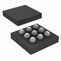
Physical Dimensions www.national.com inches (millimeters) unless otherwise noted 9-Bump Thin Micro SMD, Large Bump X1 = 1.946mm ± 0.030mm X2 = 1.946mm ±0.030mm X3 = 0.600mm ±0.075mm 22 ...
Page 23
Notes 23 www.national.com ...
Page 24
... National Semiconductor and the National Semiconductor logo are registered trademarks of National Semiconductor Corporation. All other brand or product names may be trademarks or registered trademarks of their respective holders. ...