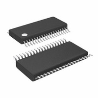
LTC3865EFE#PBF Linear Technology, LTC3865EFE#PBF Datasheet - Page 32

LTC3865EFE#PBF
Manufacturer Part Number
LTC3865EFE#PBF
Description
IC BUCK SYNC ADJ DUAL 38TSSOP
Manufacturer
Linear Technology
Type
Step-Down (Buck)r
Datasheet
1.LTC3865EUHPBF.pdf
(38 pages)
Specifications of LTC3865EFE#PBF
Internal Switch(s)
No
Synchronous Rectifier
Yes
Number Of Outputs
2
Voltage - Output
0.6 ~ 5 V
Frequency - Switching
250kHz ~ 770kHz
Voltage - Input
4.5 ~ 38 V
Operating Temperature
-40°C ~ 85°C
Mounting Type
Surface Mount
Package / Case
38-TSSOP Exposed Pad, 38-eTSSOP, 38-HTSSOP
Primary Input Voltage
15V
No. Of Outputs
2
Output Voltage
5V
Output Current
25A
No. Of Pins
38
Operating Temperature Range
-40°C To +85°C
Msl
MSL 1 - Unlimited
Rohs Compliant
Yes
Lead Free Status / RoHS Status
Lead free / RoHS Compliant
Current - Output
-
Power - Output
-
Available stocks
Company
Part Number
Manufacturer
Quantity
Price
APPLICATIONS INFORMATION
LTC3865/LTC3865-1
With I
can be calculated by using the minimum value for the
maximum current sense threshold (44mV).
The equivalent R
The Coiltronics (Cooper) HCP0703-2R2 (20mΩ DCR
at 20°C) and HCP0703-3R3 (30mΩ DCR
chosen. At 100°C, the estimated maximum DCR values are
26.4mΩ and 39.6mΩ. The divider ratios are:
For each channel, 0.1μF is selected for C1.
For channel 1, the DCR
32
R
R
R R
R
R
and
D
1
1
2
SENSE EQUIV
||
=
=
LIM
=
R R
R
DCR
2
1
39 6
1
1
R
(
7 7
=
fl oating, the equivalent R
=
−
||
R
•
.
D
1
.
R
(
R
SENSE EQUIV
MAX
DCR
. . ;
m
2 1 1
D
1
m
D
k
Ω
=
)
Ω
=
SENSE
=
=
MAX
at T
0 2
(
5 5
.
5
≅
I
.
and
.
LOAD MAX
1 0 2
A
k
0 2
44
L MAX
−
k
(
+
.
at
L
is the same for Channel 2.
≅
SENSE
• 0 0 2
mV
)
1 5
(
.
V
20
5 5
.
SENSE MIN
30
.
2
.
)
°
A
k
C C
=
m
fi lter/divider values are:
≅
)
;
) •
3 3
≅
+
26 4
Ω
1 37
.
7 7
(
7 7
.
Δ
.
.
• .
.
μ
1
I
0 1
m
L NOM
H
mΩ
=
k
m
SENSE
)
(
2
Ω
Ω
20
μ
F
MAX
= =
m
) )
=
2 2
0 3
resistor value
Ω
.
1 1
. ;
at 20°C) are
.
μ
• .
0 1
H
k
μ
F
MAX
The power loss in R1 at the maximum input voltage is:
The respective values for Channel 2 are R1 = 3.66k,
R2 = 1.57k; and P
Burst Mode operation is chosen for high light load effi ciency
(Figure 15) by fl oating the MODE/PLLIN pin. Power loss
due to the DCR sensing network is slightly higher at light
loads than would have been the case with a suitable sense
resistor (8mΩ). At heavier loads, DCR sensing provides
higher effi ciency.
The power dissipation on the topside MOSFET can be easily
estimated. Choosing a Siliconix Si4816BDY dual MOSFET
results in: R
At maximum input voltage with T(estimated) = 50°C:
P
P
(
⎡
⎢
⎣
0 0
LOSS
MAIN
5 2 3
. 2 2 3
– .
1
Figure 15. Design Example Effi ciency vs Load
R
=
Ω
1
100
90
80
70
60
50
40
3 3
=
20
=
+
)
0.01
DS(ON)
.
+
(
(
2
20
V
V
V
1
(
. . 3
IN MAX
20
( )
V
EFFICIENCY
⎤
⎥
⎦
(
5
LOSS
(
V
−
= 0.023Ω/0.016Ω, C
500
2
)
3 3
5 5
[
2
LOAD CURRENT (mA)
.
1 0 005 50
0.1
)
.
⎛
⎝ ⎜
R1 = 8mW.
−
+
kHz
V
k
5
R
( .
2
V
) •
A
1
OUT
)
⎞
⎠ ⎟
3
=
( )(
. .
2
3
186
) •
Ω
V
)(
POWER LOSS
1
V
=
OUT
mW
100
10
°
C
mW
DCR
8mΩ
–
pF •
MILLER
3865 F16
25
10
)
°
10
1
0.1
0.01
C
) •
]
≅ 100pF.
3865fb


