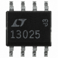
LT1302CS8-5#TR Linear Technology, LT1302CS8-5#TR Datasheet

LT1302CS8-5#TR
Specifications of LT1302CS8-5#TR
Available stocks
Related parts for LT1302CS8-5#TR
LT1302CS8-5#TR Summary of contents
Page 1
... Quiescent current is just 200 A and can be further reduced shutdown. Available in 8-pin PDIP or 8-pin SO packaging, the LT1302/ LT1302-5 have the highest switch current rating of any similarly packaged switching regulators presently on the market. , LTC and LT are registered trademarks of Linear Technology Corporation. Burst Mode is a trademark of Linear Technology Corporation ...
Page 2
... Note 3: Minimum switch current 100% tested. Maximum switch current guaranteed by design TOP VIEW ORDER PART NUMBER PGND LT1302CN8 V 6 LT1302CS8 LT1302CN8-5 T LT1302CS8-5 S8 PACKAGE 8-LEAD PLASTIC SO *FIXED VERSION S8 PART MARKING 1302 = 100 C/W (N8) JA 13025 = 80 C/W (S8) JA MIN TYP MAX 200 300 15 25 2.0 2 ...
Page 3
W U TYPICAL PERFORMANCE CHARACTERISTICS No-Load Quiescent Current Circuit of Figure 1 500 450 400 350 300 250 200 150 100 50 0 2.0 2.5 3.0 3.5 4.0 4.5 SUPPLY VOLTAGE (V) 1302 G01 LT1302 ...
Page 4
LT1302/LT1302 TYPICAL PERFORMANCE CHARACTERISTICS Maximum Duty Cycle 100 –50 – 100 TEMPERATURE ( C) 1302 G10 LT1302-5 Output Voltage vs Load Current 5.20 5.15 5.10 5.05 5.00 4.95 V ...
Page 5
CTIO S SW (Pin 7): Switch Pin. Connect inductor and diode here. Keep layout short and direct. PGND (Pin 8): Power Ground. Pins 8 and 1 should be connected under the package. In the SO ...
Page 6
LT1302/LT1302-5 W BLOCK DIAGRA SM SENSE 4 R1 315k 1.24V REFERENCE R2 105k SHDN 3 SHUTDOWN 1 GND U OPERATIO The LT1302’s operation can best be understood by examining the block diagram in Figure 2. The LT1302 operates in one ...
Page 7
U OPERATIO CMP1 stays on and the peak switch current is regulated by the voltage on the V pin (A1’s output base of Q1. As the V voltage rises, Q2 conducts less C current, resulting in less drop ...
Page 8
LT1302/LT1302 APPLICATIONS INFORMATION and there is no low frequency component. The total ESR is under 0. single 100 F aluminum electrolytic capacitor is used instead, the converter mode-hops be- tween current mode and Burst Mode ...
Page 9
U U APPLICATIONS INFORMATION Frequency Compensation Obtaining proper RC values for the frequency compensa- tion network is largely an empirical procedure, since variations in input and output voltage, topology, capacitor ESR and inductance make a simple formula elusive ...
Page 10
LT1302/LT1302 APPLICATIONS INFORMATION V OUT 100mV/DIV AC COUPLED 510mA I LOAD 10mA 2ms/DIV Figure 7c. 0.01 F from V C Underdamped Response Requires Series R V OUT 100mV/DIV AC COUPLED 510mA I LOAD 10mA 2ms/DIV Figure 7d. 0.1 ...
Page 11
U U APPLICATIONS INFORMATION ally reaches audio frequencies, but at a much lighter load than without the I feature. At some input voltage/load T current combinations, some residual bursting may occur at frequencies out of the audio band. V OUT ...
Page 12
LT1302/LT1302 APPLICATIONS INFORMATION separate ground trace up under the package as shown. The battery and load return should go to the power side of the ground copper. Thermal Considerations The LT1302 contains a thermal shutdown feature which protects ...
Page 13
U U APPLICATIONS INFORMATION As an example, consider a boost converter with the following specifications OUT I = 700mA OUT Total power loss in the LT1302, assuming R = 0.15 and V = ...
Page 14
LT1302/LT1302-5 U TYPICAL APPLICATIONS 220 1.5V CELL SET LT1073 FB GND SW2 L1 = COILCRAFT DO3316-332 D1 = MOTOROLA MBRS130LT3 + C1 2 CELLS 100 F OUTPUT 12V 120mA 14 Single Cell to 5V/150mA Converter 5V/150mA OUTPUT ...
Page 15
... L1, L2=COILCRAFT DO3316-223 C1=AVX TPSE107016R0100 C2, C3=AVX TPSE227010R0100 Information furnished by Linear Technology Corporation is believed to be accurate and reliable. However, no responsibility is assumed for its use. Linear Technology Corporation makes no represen- tation that the interconnection of its circuits as described herein will not infringe on existing patent rights ...
Page 16
... MIN (0.380) MIN 0.018 0.003 (0.457 0.076) N8 0694 6 5 0.150 – 0.157* (3.810 – 3.988 0.004 – 0.010 (0.101 – 0.254) 0.050 (1.270) BSC SO8 0294 LT/GP 0295 10K • PRINTED IN USA LINEAR TECHNOLOGY CORPORATION 1995 ...


