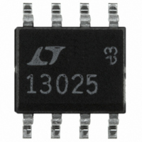
LT1302CS8-5#TR Linear Technology, LT1302CS8-5#TR Datasheet - Page 10

LT1302CS8-5#TR
Manufacturer Part Number
LT1302CS8-5#TR
Description
IC CONV DC/DC STEP UP 5V 8SOIC
Manufacturer
Linear Technology
Type
Step-Up (Boost)r
Datasheet
1.LT1302CS8-5PBF.pdf
(16 pages)
Specifications of LT1302CS8-5#TR
Internal Switch(s)
Yes
Synchronous Rectifier
No
Number Of Outputs
1
Voltage - Output
5V
Current - Output
600mA
Frequency - Switching
220kHz
Voltage - Input
2 ~ 8 V
Operating Temperature
0°C ~ 70°C
Mounting Type
Surface Mount
Package / Case
8-SOIC (3.9mm Width)
Power - Output
700mW
Lead Free Status / RoHS Status
Contains lead / RoHS non-compliant
Available stocks
Company
Part Number
Manufacturer
Quantity
Price
APPLICATIONS
LT1302/LT1302-5
10
I
I
I
AC COUPLED
AC COUPLED
LOAD
LOAD
AC COUPLED
LOAD
AC COUPLED
I
100mV/DIV
100mV/DIV
LOAD
100mV/DIV
100mV/DIV
510mA
510mA
510mA
10mA
510mA
10mA
V
10mA
V
V
V
10mA
OUT
OUT
OUT
OUT
Figure 7e. 0.01 F, 10k Series RC Shows Good
Transient Response. Slight Underdamping
Still Noticeable
Figure 7c. 0.01 F from V
Underdamped Response Requires Series R
Figure 7d. 0.1 F with 10k Series RC.
Classic Overdamped Response
Figure 7f. 0.01 F, 24k Series RC
Results in Optimum Response
U
INFORMATION
U
2ms/DIV
2ms/DIV
2ms/DIV
2ms/DIV
C
to Ground.
W
1302 F07c
1302 F07d
1302 F07e
1302 F07f
U
2.5V
V
IN
I
The I
LT1302 to operate in current mode even at light load. To
disable Burst Mode, 3.3k resistor R1 is connected from I
to gound. More conservative frequency compensation
must be used when in this mode. A 0.1 F capacitor and
4.7k resistor from V
adequate. Low frequency Burst Mode ripple can be
reduced or eliminated using this technique in many appli-
cations.
To illustrate, the transient load response of Figure 8’s
circuit is pictured without and with R1. Figure 8a shows
output voltage and inductor current without the resistor.
Note the 6kHz burst rate when the converter is delivering
25mA. By adding the 3.3k resistor, the low frequency
bursting is eliminated, as shown in Figure 8b. This feature
is useful in systems that contain audio circuitry. At very
light or zero load, switching frequency drops and eventu-
T
+
Pin
I
AC COUPLED
LOAD
600mA
100mV/DIV
INDUCTOR
V
CURRENT
C1
330 F
5V
OUT
T
1A/DIV
525mA
Figure 8a. I
I
Causes 220mV Undershoot
Figure 8. Addition of R1 Eliminates Low Frequency
Output Ripple in This 2.5V to 5V Boost Converter
LOAD
25mA
pin is used to disable Burst Mode, forcing the
V
+
OUT
MBRS130LT3
= 25mA. 0.1 F/4.7k Compensation Network
220 F
10V
T
Pin Floating. Note 6kHz Burst Rate at
+
C
10 H
220 F
10V
to ground has been found to be
1ms/DIV
0.1 F
SW
PGND
GND
V
IN
LT1302-5
SENSE
1302 F08a
I
T
V
R1
3.3k
C
1302 F08
4.7k
0.1 F
T


