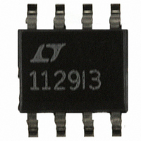
LT1107CS8 Linear Technology, LT1107CS8 Datasheet - Page 5

LT1107CS8
Manufacturer Part Number
LT1107CS8
Description
IC DC/DC CONV ADJUSTBL OUT 8SOIC
Manufacturer
Linear Technology
Type
Step-Down (Buck), Step-Up (Boost), Invertingr
Datasheet
1.LT1107CS8PBF.pdf
(16 pages)
Specifications of LT1107CS8
Internal Switch(s)
Yes
Synchronous Rectifier
No
Number Of Outputs
1
Voltage - Output
Adjustable
Current - Output
400mA
Frequency - Switching
63kHz
Voltage - Input
2 ~ 30 V
Operating Temperature
0°C ~ 70°C
Mounting Type
Surface Mount
Package / Case
8-SOIC (3.9mm Width)
Power - Output
500mW
Lead Free Status / RoHS Status
Contains lead / RoHS non-compliant
Available stocks
Company
Part Number
Manufacturer
Quantity
Price
Company:
Part Number:
LT1107CS8
Manufacturer:
LT
Quantity:
5 510
Part Number:
LT1107CS8
Manufacturer:
LINEAR/凌特
Quantity:
20 000
Part Number:
LT1107CS8#PBF
Manufacturer:
LINEAR/凌特
Quantity:
20 000
Part Number:
LT1107CS8#TRPBF
Manufacturer:
LINEAR/凌特
Quantity:
20 000
Part Number:
LT1107CS8-12
Manufacturer:
LINEAR/凌特
Quantity:
20 000
Part Number:
LT1107CS8-12#PBF
Manufacturer:
LINEAR/凌特
Quantity:
20 000
PI
I
lower current limit is desired, connect a resistor between
I
to approximately 400mA.
V
SW1 (Pin 3): Collector of Power Transistor. For step-up
mode connect to inductor/diode. For step-down mode
connect to V
SW2 (Pin 4): Emitter of Power Transistor. For step-up
mode connect to ground. For step-down mode connect to
inductor/diode. This pin must never be allowed to go more
than a Schottky diode drop below ground.
TYPICAL PERFOR
LIM
LIM
IN
100
5.3
5.2
5.1
5.0
4.9
4.8
4.7
U
90
80
70
60
50
40
30
(Pin 2): Input Supply Voltage.
(Pin 1): Connect this pin to V
–55
and V
Minimum/Maximum Frequency
vs ON Time, Step-Down Mode
LT1107-5
Output Voltage
4
–55 C T
FU
–35
5
IN
–15
6
U
. A 220 resistor will limit the switch current
A
IN
C
TEMPERATURE ( C)
7
.
5
125 C
TI
ON TIME ( s)
8
25
O
9
45
U
10
S
65
0 C T
11
85 105
W
12
A
1107 G16
A
70 C
13 14
1107 G11
IN
U
125
for normal use. Where
CE
C
12.20
12.15
12.10
12.05
12.00
11.95
11.90
11.85
11.80
HARA TERISTICS
100
90
80
70
60
50
40
30
–55
Minimum/Maximum Frequency
vs ON Time, Step-Up Mode
LT1107-12
Output Voltage
6
–35
–55 C T
7
–15
C
8
T
A
= 25 C
TEMPERATURE ( C)
9
A
5
ON TIME ( s)
125 C
10
25
0 C T
11
GND (Pin 5): Ground.
AO (Pin 6): Auxiliary Gain Block (GB) Output. Open collector,
can sink 300 A.
SET (Pin 7): GB Input. GB is an op amp with positive input
connected to SET pin and negative input connected to
1.25V reference.
FB/SENSE (Pin 8): On the LT1107 (adjustable), this pin
goes to the comparator input. On the LT1107-5 and
LT1107-12, this pin goes to the internal application resistor
that sets output voltage.
45
12
A
65
70 C
13
85 105
14
1107 G17
15 16
1107 G12
125
1.30
1.29
1.28
1.27
1.26
1.25
1.24
1.23
1.22
1.21
1.20
70
65
60
55
50
45
40
35
–55
–55
Duty Cycle
Step-Down Mode
LT1107
Feedback Voltage
–35
–35
–15
–15
TEMPERATURE ( C)
TEMPERATURE ( C)
5
5
25
25
45
45
65
65
LT1107
85 105
85 105
1107 G13
1107 G18
1107fa
5
125
125


