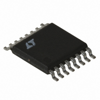
LT1977EFE#TR Linear Technology, LT1977EFE#TR Datasheet - Page 12

LT1977EFE#TR
Manufacturer Part Number
LT1977EFE#TR
Description
IC REG SW 1.5A HV STPDWN 16TSSOP
Manufacturer
Linear Technology
Type
Step-Down (Buck)r
Datasheet
1.LT1977EFEPBF.pdf
(24 pages)
Specifications of LT1977EFE#TR
Internal Switch(s)
Yes
Synchronous Rectifier
No
Number Of Outputs
1
Voltage - Output
1.2 ~ 54 V
Current - Output
1.5A
Frequency - Switching
500kHz
Voltage - Input
3.3 ~ 60 V
Operating Temperature
-40°C ~ 125°C
Mounting Type
Surface Mount
Package / Case
16-TSSOP Exposed Pad, 16-eTSSOP, 16-HTSSOP
Lead Free Status / RoHS Status
Contains lead / RoHS non-compliant
Power - Output
-
Available stocks
Company
Part Number
Manufacturer
Quantity
Price
LT1977
APPLICATIO S I FOR ATIO
triangular with a typical value of 200mA
to calculate this is:
CERAMIC CAPACITORS
Higher value, lower cost ceramic capacitors are now
becoming available. They are generally chosen for their
good high frequency operation, small size and very low
ESR (effective series resistance). Low ESR reduces output
ripple voltage but also removes a useful zero in the loop
frequency response, common to tantalum capacitors. To
compensate for this a resistor R
with the V
must be taken however since this resistor sets the high
frequency gain of the error amplifier including the gain at
the switching frequency. If the gain of the error amplifier
is high enough at the switching frequency output ripple
voltage (although smaller for a ceramic output capacitor)
may still affect the proper operation of the regulator. A
filter capacitor C
with a small feedforward capacitor C
control possible ripple at the V
stabilized using a 100µF ceramic output capacitor and V
component values of C
and C
OUTPUT RIPPLE VOLTAGE
Figure 3 shows a typical output ripple voltage waveform
for the LT1977. Ripple voltage is determined by the
impedance of the output capacitor and ripple current
through the inductor. Peak-to-peak ripple current through
the inductor into the output capacitor is:
For high frequency switchers the ripple current slew rate
is also relevant and can be calculated from:
12
Output capacitor ripple current (RMS)
I
I
dt
RIPPLE RMS
P-P
di
FB
=
=
= 10pF.
V
L
(
V
IN
C
OUT
compensation capacitor C
( )( )( )
V
)
(
IN
V
=
F
IN
in parallel with the R
0 29
L f
U
–
.
V
OUT
(
C
V
= 1500pF, R
( )( )( )
OUT
U
L f V
)
)(
C
V
IN
C
pin. The LT1977 can be
IN
can be placed in series
–
W
V
C
C
FB
OUT
C
/C
= 10k, C
RMS
, is suggested to
(Figure 10). Care
C
)
network, along
. The formula
=
I
U
P-P
F
12
= 330pF
C
Peak-to-peak output ripple voltage is the sum of a triwave
created by peak-to-peak ripple current times ESR and a
square wave created by parasitic inductance (ESL) and
ripple current slew rate. Capacitive reactance is assumed
to be small compared to ESR or ESL.
Example: with V
0.08Ω, ESL = 10nH:
MAXIMUM OUTPUT LOAD CURRENT
Maximum load current for a buck converter is limited by
the maximum switch current rating (I
specified current rating for the LT1977 is 1.5A. Unlike
most current mode converters, the LT1977 maximum
switch current limit does not fall off at high duty cycles.
Most current mode converters suffer a drop off of peak
switch current for duty cycles above 50%. This is due to
the effects of slope compensation required to prevent
subharmonic oscillations in current mode converters.
(For detailed analysis, see Application Note 19.)
TANTALUM
V
I
V
dt
10mV/DIV
10mV/DIV
P-P
di
CERAMIC
RIPPLE
RIPPLE
10V/DIV
75mΩ
100µF
100µF
=
V
V
V
=
OUT
OUT
SW
15
( )
Figure 3. LT1977 Ripple Voltage Waveform
12 15
V
V
I
L
12
= (0.319A)(0.08) + (10e – 9)(0.8e6)
= 0.026 + 0.008 = 34mV
e
IN
OUT
=
= 1A
–
( )(
= 12V
( )(
3 3 12 3 3
(
= 3.3V
I
6
P-P
.
IN
=
e
= 12V, V
0 8 6
−
ESR
.
6 500 3
– .
e
)(
)
500ns/DIV
+
)
(
OUT
e
ESL
)
= 3.3V, L = 15µH, ESR =
=
)
dt
di
0 319
P-P
.
PK
). The minimum
A
1977 F03
1977fa


