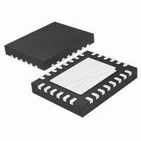
LTC3546IUFD#PBF Linear Technology, LTC3546IUFD#PBF Datasheet - Page 15

LTC3546IUFD#PBF
Manufacturer Part Number
LTC3546IUFD#PBF
Description
IC BUCK SYNC ADJ 1A/2A DL 28QFN
Manufacturer
Linear Technology
Type
Step-Down (Buck)r
Datasheet
1.LTC3546EUFDTRPBF.pdf
(28 pages)
Specifications of LTC3546IUFD#PBF
Internal Switch(s)
Yes
Synchronous Rectifier
Yes
Number Of Outputs
2
Voltage - Output
0.6 ~ 5 V
Current - Output
1A, 2A
Frequency - Switching
2.25MHz, 0.75MHz ~ 4MHz
Voltage - Input
2.25 ~ 5.5 V
Operating Temperature
-40°C ~ 125°C
Mounting Type
Surface Mount
Package / Case
28-QFN
Dc To Dc Converter Type
Step Down
Pin Count
28
Input Voltage
5.5V
Output Voltage
0.6 to 5V
Switching Freq
750 TO 4000/2900KHz
Output Current
2A
Efficiency
96%
Package Type
QFN EP
Output Type
Adjustable
Switching Regulator
Yes
Load Regulation
0.2%
Line Regulation
0.2%/V
Mounting
Surface Mount
Input Voltage (min)
2.25V
Operating Temperature Classification
Automotive
Lead Free Status / RoHS Status
Lead free / RoHS Compliant
Power - Output
-
Lead Free Status / Rohs Status
Compliant
Available stocks
Company
Part Number
Manufacturer
Quantity
Price
APPLICATIONS INFORMATION
Burst Mode Operation Considerations
There are two factors that determine the load current at which
the LTC3546 enters Burst Mode operation: the inductor value
and the BMC pin voltage. The transition from low current
operation begins when the peak inductor current falls below
a level set by the burst clamp. Lower inductor values result in
higher ripple current which causes Burst Mode operation to
occur at lower load currents. Lower inductor values will also
cause a dip in effi ciency in the upper range of low current
operation. Lower inductor values will also cause the burst
frequency to increase in Burst Mode operation.
The burst clamp level can be set by the voltage on the BMC
pin. If BMC is tied to V
BMC pin voltage between 0V and 0.6V will set the burst
clamp level (see charts OUT1 Minimum Peak Current vs
V
Typical Performance Characteristics section). Generally, a
higher clamp level results in improved light load effi ciency
and higher output voltage ripple, while a lower clamp level
results in small output voltage ripple at the expense of
effi ciency. The BMC pin should be connected to ground
when Burst Mode operation is not selected.
Table 1.
MANUFACTURER
Würth Elektronik
Würth Elektronik
Vishay
Vishay
Coilcraft
Coilcraft
Coiltronics
Coiltronics
Sumida
BMC1
and OUT2 Minimum Peak Current vs V
CDRH3D23NP-1R5NC
IHLP-1616AB-11
IHLP-1616AB-11
IN
PART NUMBER
DO1813H-561
74477450056
LPS6225-122
7447745012
WE-PD2 MS
WE-PD2 MS
, an internally set level is used. A
SD20-1R2
SD20-R47
VALUE (μH)
0.56
0.47
0.56
0.47
BMC2
1.2
1.2
1.2
1.2
1
in the
MAX DC CURRENT (A)
Inductor Core Selection
Different core materials and shapes will change the size/cur-
rent relationship of an inductor. Toroid or shielded pot cores
in ferrite or permalloy materials are small and don’t radiate
much energy, but generally cost more than powdered iron
core inductors with similar electrical characteristics. The
choice of which style inductor to use often depends more
on the price vs size requirements of any radiated fi eld/EMI
requirements than on what the LTC3546 requires to oper-
ate. Table 1 shows some typical surface mount inductors
that work well in LTC3546 applications.
Input Capacitor (C
In continuous mode, the input current of the converter can
be approximated by the sum of two square waves with
duty cycles of approximately V
prevent large voltage transients, a low equivalent series
resistance (ESR) input capacitor sized for the maximum
RMS current must be used. Some capacitors have a de-
rating spec for maximum RMS current. If the capacitor
being used has this requirement it is necessary to calculate
3.75
2.55
4.6
6.5
5.4
7.7
2.8
6
4
0.0078
0.0275
IN
0.017
0.068
0.019
0.025
DCR
0.04
0.01
0.02
) Selection
DIMENSIONS L × W × H (mm)
OUT1
4.06 × 4.45 × 1.20
4.06 × 4.45 × 1.20
6.10 × 8.89 × 5.00
/V
6.2 × 6.2 × 2.5
3.8 × 3.8 × 2.3
5.2 × 5.8 × 2
5.2 × 5.8 × 2
5.2 × 5.2 × 2
5.2 × 5.2 × 2
IN
and V
LTC3546
OUT2
15
/V
IN
3546fb
. To


