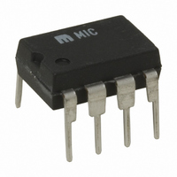
MIC3172YN Micrel Inc, MIC3172YN Datasheet - Page 15

MIC3172YN
Manufacturer Part Number
MIC3172YN
Description
IC REG SW 100KHZ 1.25A 8-DIP
Manufacturer
Micrel Inc
Type
Step-Down (Buck), Step-Up (Boost), Inverting, Cukr
Specifications of MIC3172YN
Internal Switch(s)
Yes
Synchronous Rectifier
No
Number Of Outputs
1
Current - Output
1.25A
Frequency - Switching
100kHz
Voltage - Input
3 ~ 40 V
Operating Temperature
-40°C ~ 85°C
Mounting Type
Through Hole
Package / Case
8-DIP (0.300", 7.62mm)
Power - Output
302mW
Primary Input Voltage
40V
No. Of Outputs
1
Output Current
3A
No. Of Pins
8
Operating Temperature Range
-40°C To +85°C
Supply Voltage Range
3V To 40V
Termination Type
Through Hole
Lead Free Status / RoHS Status
Lead free / RoHS Compliant
Voltage - Output
-
Lead Free Status / RoHS Status
Lead free / RoHS Compliant, Lead free / RoHS Compliant
Other names
576-2255
MIC3172YN
MIC3172YN
MIC2172/3172
50%, the MIC2172 (and MIC3172) has a maximum duty cycle
capability of 90%. If 90% was required during operation
(start-up and high load currents), a complete reset of the
transformer during the off-time would require the voltage
across the power switch to be ten times the input voltage.
This would limit the input voltage to 6V or less for forward
converter applications.
To prevent core saturation, the application given here uses a
duty cycle limiter consisting of Q1, C4 and R3. Whenever the
MIC3172 exceeds a duty cycle of 50%, T1’s reset winding
current turns Q1 on. This action reduces the duty cycle of the
MIC3172 until T1 is able to reset during each cycle.
Fluorescent Lamp Supply
An extremely useful application of the MIC3172 is generating
an ac voltage for fluorescent lamps used as liquid crystal
display back lighting in portable computers.
Figure 15 shows a complete power supply for lighting a
fluorescent lamp. Transistors Q1 and Q2 together with ca-
pacitor C2 form a Royer oscillator. The Royer oscillator
generates a sine wave whose frequency is determined by the
series L/C circuit comprised of T1 and C2. Assuming that the
MIC3172 and L1 are absent, and the transistors’ emitters are
grounded, circuit operation is described in “Oscillator Opera-
tion.”
Oscillator Operation
Resistor R2 provides initial base current that turns transistor
Q1 on and impresses the input voltage across one half of T1’s
primary winding (Pri 1). T1’s feedback winding provides
additional base drive (positive feedback) to Q1 forcing it well
April 2005
Shutdown
Enable
12V
V
IN
C1
22µF
Figure 14. 12V to 5V Forward Converter
EN
P1 P2 S
GND
MIC3172
V
1µF
IN
C3
R2
COMP
1k
V
R1*
FB
SW
* Voltage clipper
†
Q1
Duty cycle limiter
1N5819
†
1:1:1
15
C2*
D1*
T1
C4
D2
R3
into saturation for a period determined by the Pri 1/C2 time
constant. Once the voltage across C2 has reached its
maximum circuit value, Q1’s collector current will no longer
increase. Since T1 is in series with Q1, this drop in primary
current causes the flux in T1 to change and because of the
mutual coupling to the feedback winding further reduces
primary current eventually turning Q1 off. The primary wind-
ings now change state with the feedback winding forcing Q2
on repeating the alternate half cycle exactly as with Q1. This
action produces a sinusoidal voltage wave form; whose
amplitude is proportional to the input voltage, across T1’s
primary winding which is stepped up and capacitively coupled
to the lamp.
Lamp Current Regulation
Initial ionization (lighting) of the fluorescent lamp requires
several times the ac voltage across it than is required to
sustain current through the device. The current through the
lamp is sampled and regulated by the MIC3172 to achieve a
given intensity. The MIC3172 uses L1 to maintain a constant
average current through the transistor emitters. This current
controls the voltage amplitude of the Royer oscillator and
maintains the lamp current. During the negative half cycle,
lamp current is rectified by D3. During the positive half cycle,
lamp current is rectified by D2 through R4 and R5. R3 and C5
filter the voltage dropped across R4 and R5 to the MIC3172’s
feedback pin. The MIC3172 maintains a constant lamp
current by adjusting its duty cycle to keep the feedback
voltage at 1.24V. The intensity of the lamp is adjusted using
potentiometer R5.
accordingly to bring the average voltage across R4 and R5
back to 1.24V.
†
†
1N5819
D3
1N5819
L1 100µH
D4
The MIC3172 adjusts its duty cycle
470µF
C5
R4
3.74k
1%
R5
1.24k
1%
V
5V, 1A
OUT
M9999-042205
Micrel, Inc.


