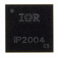
IP2004TR International Rectifier, IP2004TR Datasheet - Page 6

IP2004TR
Manufacturer Part Number
IP2004TR
Description
IC PWR BLOCK MULTIPHASE 40A LGA
Manufacturer
International Rectifier
Series
iPOWIR™r
Type
Step-Down (Buck)r
Datasheet
1.IP2004TR.pdf
(15 pages)
Specifications of IP2004TR
Internal Switch(s)
Yes
Synchronous Rectifier
Yes
Number Of Outputs
1
Voltage - Output
0.8 ~ 8 V
Current - Output
40A
Frequency - Switching
250kHz ~ 1.5MHz
Voltage - Input
3.3 ~ 13.2 V
Operating Temperature
-40°C ~ 125°C
Mounting Type
Surface Mount
Package / Case
Power Block (LGA)
Power - Output
7.4W
Lead Free Status / RoHS Status
Lead free / RoHS Compliant
Applying the Safe Operating Area (SOA) Curve
The SOA graph incorporates power loss and thermal resistance information in a way that
allows one to solve for maximum current capability in a simplified graphical manner. It
incorporates the ability to solve thermal problems where heat is drawn out through the printed
circuit board and the top of the case. Please refer to International Rectifier Application Note
AN1047 for further details on using this SOA curve in your thermal environment.
Procedure
Page 6 of 15
Average
Voltage
VDD
1. Calculate (based on estimated Power Loss) or measure the Case temperature on the
2. Draw a line from Case Temperature axis to the PCB Temperature axis.
3. Draw a vertical line from the T
4. Draw a horizontal line from the intersection of the vertical line with the SOA curve to
P
P
P
P
V
device and the Board temperature near the device (1mm from the edge).
the Y-axis (Output Current). The point at which the horizontal line meets the Y-axis is
the SOA continuous current.
IN
DD
OUT
LOSS
= V
= V
DC
= V
= (P
IN
DD
Figure 9 Power Loss Test Circuit
OUT
Average
Current
Average x I
VDD
IN
Average x I
A
Figure 11 SOA Example, Continuous current ≈ 30A for T
Average x I
+ P
DD
) - P
V
ENABLE
PWM
P
IN
DD
GND
NC
OUT
DD
Average
iP2004
OUT
V
Average
SWS1
Average
V
SWS2
P
V
GND
V
SW
IN
44
40
36
32
28
24
20
16
12
8
4
0
0
0
Average
Current
Input
L
F
V
V
A
sw
O
V
10
D
O
10
I
= 300nH
= 12V
= 5.0V
= 1.3V
= 1MHz
Averaging
Circuit
20
20
Average Output
www.irf.com
Current
30
30
Operating
V
A
X
DC
Area
Safe
axis intercept to the SOA curve.
Average
40
Voltage
Output
40
V
50
50
Case Temperature (ºC)
PCB Temperature (ºC)
Average
Voltage
Input
60
60
70
70
80
80
PWM
90
V
90
SW
100
100
PCB
Figure 10 Timing Diagram
110
110
= 95ºC & T
t
PDH
120
120
90%
10%
130
130
Data Sheet No. PD60322
Tx
12/22/2007
CASE
= 110ºC
iP2004
t
PDL
10%
90%


