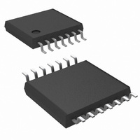
LM2743MTCX/NOPB National Semiconductor, LM2743MTCX/NOPB Datasheet - Page 13

LM2743MTCX/NOPB
Manufacturer Part Number
LM2743MTCX/NOPB
Description
IC REG CTLR BUCK N-CH 14-TSSOP
Manufacturer
National Semiconductor
Series
PowerWise®r
Type
Step-Down (Buck)r
Datasheet
1.LM2743MTCNOPB.pdf
(26 pages)
Specifications of LM2743MTCX/NOPB
Internal Switch(s)
No
Synchronous Rectifier
Yes
Number Of Outputs
1
Voltage - Output
0.6 ~ 13.5 V
Current - Output
20A
Frequency - Switching
50kHz ~ 1MHz
Voltage - Input
1 ~ 16 V
Operating Temperature
-40°C ~ 125°C
Mounting Type
Surface Mount
Package / Case
14-TSSOP
For Use With
LM2743EVAL - BOARD EVALUATION LM2743LM2743-19AEVAL - BOARD EVALUATION LM2743-19A
Lead Free Status / RoHS Status
Lead free / RoHS Compliant
Power - Output
-
Other names
LM2743MTCX
Available stocks
Company
Part Number
Manufacturer
Quantity
Price
Company:
Part Number:
LM2743MTCX/NOPB
Manufacturer:
UNITRODE
Quantity:
6 218
Part Number:
LM2743MTCX/NOPB
Manufacturer:
TI/德州仪器
Quantity:
20 000
Figure 9
MOSFET drives using a doubler. This circuit provides an
equal voltage drive of V
and low-side MOSFET drives. This method should only be
used in circuits that use 3.3V for both V
V
both high-side and low-side gates will have at least 4.5V of
drive. The power dissipation of the gate drive circuitry is di-
rectly proportional to gate drive voltage, hence the thermal
limits of the LM2743 IC will quickly be reached if this circuit is
used with V
All the gate drive circuits shown in the above figures typically
use 100 nF ceramic capacitors in the bootstrap locations.
POWER GOOD SIGNAL
The open drain output on the Power Good pin needs a pull-
up resistor to a low voltage source. The pull-up resistor should
be chosen so that the current going into the Power Good pin
is less than 1 mA. A 100 kΩ resistor is recommended for most
applications.
IN
= V
FIGURE 8. LM78L05 Feeding Basic Charge Pump
FIGURE 9. Charge Pump with Added Gate Drive
CC
= 3.0V (10% lower tolerance on 3.3V) and V
shows a second possibility for bootstrapping the
CC
or V
IN
voltages over 5V.
CC
- 3V
D
+ V
IN
CC
to both the high-side
and V
IN
20095219
. Even with
20095213
D
= 0.5V
13
The Power Good signal is an OR-gated flag which takes into
account both output over-voltage and under-voltage condi-
tions. If the feedback pin (FB) voltage is 18% above its nom-
inal value (118% x V
(72 %x V
Power Good flag can be used to signal other circuits that the
output voltage has fallen out of regulation, however the
switching of the LM2743 continues regardless of the state of
the Power Good signal. The Power Good flag will return to
logic high whenever the feedback pin voltage is between 72%
and 118% of 0.6V.
UVLO
The 2.76V turn-on threshold on V
of about 300 mV. If V
UVLO mode. UVLO consists of turning off the top and bottom
MOSFETS and remaining in that condition until V
above 2.76V. As with shutdown, the soft-start capacitor is
discharged through an internal MOSFET, ensuring that the
next start-up will be controlled by the soft-start circuitry.
CURRENT LIMIT
Current limit is realized by sensing the voltage across the low-
side MOSFET while it is on. The R
known value; hence the current through the MOSFET can be
determined as:
The current through the low-side MOSFET while it is on is also
the falling portion of the inductor current. The current limit
threshold is determined by an external resistor, R
ed between the switching node and the I
current of 40 µA is forced through R
drop. This fixed voltage is compared against V
latter is higher, the current limit of the chip has been reached.
To obtain a more accurate value for R
the operating values of R
temperatures in your application and the effect of slight pa-
rameter differences from part to part. R
using the following equation using the R
side MOSFET at it's expected hot temperature and the abso-
lute minimum value expected over the full temperature range
for the for the I
For example, a conservative 15A current limit in a 10A design
with a minimum R
sistor. To prevent the I
when the switch node goes above 9.5V, the value of the cur-
rent limit setting resistor R
criterion is as follows,
where the 10 mA is the maximum current I
to sink. For example if V
R
side MOSFET, no minimum high-side on-time is necessary.
The LM2743 enters current limit mode if the inductor current
exceeds the current limit threshold at the point where the high-
side MOSFET turns off and the low-side MOSFET turns on.
(The point of peak inductor current, see
in normal operation mode the high-side MOSFET always
CS
is 370Ω. Because current sensing is done across the low-
FB
= 0.42V) the Power Good flag goes low. The
SEN-TH
R
CS
DS(ON)
= R
FB
V
which is 25 µA:
DS
CC
= 0.708V) or falls 28% below that value
SEN
DSON-HOT
= I
drops below 2.42V, the chip enters
of 10 mΩ would require a 6 kΩ re-
DS(ON)
IN
pin from sinking too much current
OUT
CS
= 13.2V, the minimum value of
x R
should not be too low. The
and I
x I
CC
DS(ON)
DS(ON)
CS
LIM
has a built in hysteresis
SEN-TH
, causing a fixed voltage
/ 40 µA
CS
DS(ON)
Figure
CS
of the MOSFET is a
SEN
you must consider
SEN
at their operating
can be found by
pin. A constant
value of the low
pin is allowed
10). Note that
DS
CS
www.national.com
, connect-
and if the
CC
rises


