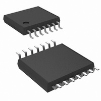
LM2743MTCX/NOPB National Semiconductor, LM2743MTCX/NOPB Datasheet - Page 14

LM2743MTCX/NOPB
Manufacturer Part Number
LM2743MTCX/NOPB
Description
IC REG CTLR BUCK N-CH 14-TSSOP
Manufacturer
National Semiconductor
Series
PowerWise®r
Type
Step-Down (Buck)r
Datasheet
1.LM2743MTCNOPB.pdf
(26 pages)
Specifications of LM2743MTCX/NOPB
Internal Switch(s)
No
Synchronous Rectifier
Yes
Number Of Outputs
1
Voltage - Output
0.6 ~ 13.5 V
Current - Output
20A
Frequency - Switching
50kHz ~ 1MHz
Voltage - Input
1 ~ 16 V
Operating Temperature
-40°C ~ 125°C
Mounting Type
Surface Mount
Package / Case
14-TSSOP
For Use With
LM2743EVAL - BOARD EVALUATION LM2743LM2743-19AEVAL - BOARD EVALUATION LM2743-19A
Lead Free Status / RoHS Status
Lead free / RoHS Compliant
Power - Output
-
Other names
LM2743MTCX
Available stocks
Company
Part Number
Manufacturer
Quantity
Price
Company:
Part Number:
LM2743MTCX/NOPB
Manufacturer:
UNITRODE
Quantity:
6 218
Part Number:
LM2743MTCX/NOPB
Manufacturer:
TI/德州仪器
Quantity:
20 000
www.national.com
turns on at the beginning of a clock cycle. In current limit
mode, by contrast, the high-side MOSFET on-pulse is
skipped. This causes inductor current to fall. Unlike a normal
operation switching cycle, however, in a current limit mode
switching cycle the high-side MOSFET will turn on as soon as
inductor current has fallen to the current limit threshold. The
LM2743 will continue to skip high-side MOSFET pulses until
the inductor current peak is below the current limit threshold,
at which point the system resumes normal operation.
Unlike a high-side MOSFET current sensing scheme, which
limits the peaks of inductor current, low-side current sensing
is only allowed to limit the current during the converter off-
time, when inductor current is falling. Therefore in a typical
current limit plot the valleys are normally well defined, but the
peaks are variable, according to the duty cycle. The PWM
error amplifier and comparator control the off-pulse of the
high-side MOSFET, even during current limit mode, meaning
that peak inductor current can exceed the current limit thresh-
old. Assuming that the output inductor does not saturate, the
maximum peak inductor current during current limit mode can
be calculated with the following equation:
Where T
ns term represents the minimum off-time of the duty cycle,
which ensures enough time for correct operation of the cur-
rent sensing circuitry.
In order to minimize the time period in which peak inductor
current exceeds the current limit threshold, the IC also dis-
charges the soft-start capacitor through a fixed 90 µA sink.
The output of the LM2743 internal error amplifier is limited by
the voltage on the soft-start capacitor. Hence, discharging the
soft-start capacitor reduces the maximum duty cycle D of the
controller. During severe current limit this reduction in duty
cycle will reduce the output voltage if the current limit condi-
tions last for an extended time. Output inductor current will be
reduced in turn to a flat level equal to the current limit thresh-
old. The third benefit of the soft-start capacitor discharge is a
SW
FIGURE 10. Current Limit Threshold
is the inverse of switching frequency f
SW
. The 200
20095288
14
smooth, controlled ramp of output voltage when the current
limit condition is cleared.
FOLDBACK CURRENT LIMIT
In the case where extra protection is used to help an output
short condition, a current foldback resistor (R
considered, see
rent limit foldback (P
where P is a ratio between 0 and 1.
Obtain the R
where I
following criterion must be satisfied:
The equation for calculating the foldback resistance value is:
SHUTDOWN
If the shutdown pin is pulled low, (below 0.8V) the LM2743
enters shutdown mode, and discharges the soft-start capac-
itor through a MOSFET switch. The high and low-side MOS-
FETs are turned off. The LM2743 remains in this state as long
as V
ble). To assure proper IC start-up the shutdown pin should
not be left floating. For normal operation this pin should be
connected directly to V
to V
DESIGN CONSIDERATIONS
The following is a design procedure for all the components
needed to create the Typical Application Circuit shown on the
front page. This design converts 3.3V (V
a maximum load of 4A with an efficiency of 89% and a switch-
ing frequency of 300 kHz. The same procedures can be
CC
SD
(see the Electrical Characteristics table).
FIGURE 11. Foldback Current Limit Circuit
sees a logic low (see the Electrical Characteristics ta-
SEN
= 40 μA. If the switch node goes above 9.5V the
CS
with the following equation:
Figure
LIM
CC
P
):
11. First select the percentage of cur-
LIM
or to another voltage between 1.3V
= I
LIM
x P
IN
) to 1.2V (V
CLF
) should be
20095295
OUT
) at


