ISL8009AIRZ-TK Intersil, ISL8009AIRZ-TK Datasheet - Page 12
ISL8009AIRZ-TK
Manufacturer Part Number
ISL8009AIRZ-TK
Description
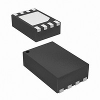
IC REG SYNC BUCK 1.5A 8-DFN
Manufacturer
Intersil
Type
Step-Down (Buck)r
Datasheet
1.ISL8009AIRZ-T.pdf
(13 pages)
Specifications of ISL8009AIRZ-TK
Internal Switch(s)
Yes
Synchronous Rectifier
Yes
Number Of Outputs
1
Voltage - Output
0.8 ~ 5.5 V
Current - Output
1.5A
Frequency - Switching
1.6MHz
Voltage - Input
2.7 ~ 5.5 V
Operating Temperature
-40°C ~ 85°C
Mounting Type
Surface Mount
Package / Case
8-DFN
Lead Free Status / RoHS Status
Lead free / RoHS Compliant
Power - Output
-
Available stocks
Company
Part Number
Manufacturer
Quantity
Price

Part Number:
ISL8009AIRZ-TK
Manufacturer:
RENESAS/瑞萨
Quantity:
20 000


Applications Information
Output Inductor and Capacitor Selection
To consider steady state and transient operation,
ISL8009A typically uses a 3.3µH output inductor. Higher
or lower inductor values can be used to optimize the total
converter system performance. For example, for higher
output voltage 3.3V application, in order to decrease the
inductor current ripple and output voltage ripple, the
output inductor value can be increased. The inductor
ripple current can be expressed in Equation 1:
ΔI
The inductor’s saturation current rating needs be at least
larger than the peak current. The ISL8009A protects the
typical peak current 2.1A. The saturation current needs
to be over 2.4A for maximum output current application.
ISL8009A uses internal compensation network and the
output capacitor value is dependant on the output
voltage. The ceramic capacitor is recommended to be
X5R or X7R. The recommended minimum output
capacitor values are shown in Table 1.
In Table 1, the minimum output capacitor value is given
for different output voltages to make sure the whole
converter system is stable.
Input Capacitor Selection
The main functions for the input capacitor are to provide
decoupling of the parasitic inductance and to provide
filtering function to prevent the switching current from
flowing back to the battery rail. A 10µF, X5R or X7R
ceramic capacitor is a good starting point for the input
capacitor selection.
Output Voltage Setting Resistor Selection
The resistors R
output voltage for the adjustable version. The output
voltage can be calculated by Equation 2:
V
O
=
=
TABLE 1. OUTPUT CAPACITOR VALUE vs V
V
-------------------------------------- -
0.8
V
O
OUT
•
L f
•
0.8
1.2
1.6
1.8
2.5
3.3
3.6
⎛
⎜
⎝
1
•
⎛
⎜
⎝
1
–
(V)
S
+
---------
V
V
R
------ -
R
IN
O
2
2
3
⎞
⎟
⎠
⎞
⎟
⎠
and R
3
shown in Figure 24 set the
C
12
OUT
10
10
10
10
10
10
10
(µF)
1.0~2.2
1.2~2.2
1.8~2.2
1.8~3.3
1.8~3.3
1.8~4.7
1.8~4.7
L (µH)
OUT
(EQ. 1)
(EQ. 2)
ISL8009A
where the 0.8V is the reference voltage.
The voltage divider consists of R
the quiescent current by VO/(R
resistance is desirable. On the other hand, the VFB pin
has leakage current that will cause error in the output
voltage setting. The leakage current has a typical value
of 0.1µA. To minimize the accuracy impact on the output
voltage, select the R
0.8V, it is recommended to short R
Layout Recommendation
The layout is a very important converter design step to
make sure the designed converter works well. For the
ISL8009A buck converter, the power loop is composed of
the output inductor L, the output capacitor C
pin and the GND pin. It is necessary to make the power
loop as small as possible.
The heat of the IC is mainly dissipated through the
thermal pad. Maximizing the copper area connected to
the thermal pad is preferable. In addition, a solid ground
plane is helpful for EMI performance. It is recommended
to add 5 vias under the thermal pad connection to the
solid ground plane.
3
no larger than 200kΩ. For V
2
2
+ R
and R
2
and open R
3
), so larger
3
and increases
November 19, 2009
OUT
3
, the LX
.
O
FN6656.2
=
Related parts for ISL8009AIRZ-TK
Image
Part Number
Description
Manufacturer
Datasheet
Request
R

Part Number:
Description:
1.5a Low Quiescent Current 1.6mhz High Efficiency Synchronous Buck Regulator
Manufacturer:
Intersil Corporation
Datasheet:
Part Number:
Description:
Intersil Corporation [CMOS Serial Controller Interface]
Manufacturer:
Intersil Corporation
Datasheet:
Part Number:
Description:
Manufacturer:
Intersil Corporation
Datasheet:
Part Number:
Description:
357-036-542-201 CARDEDGE 36POS DL .156 BLK LOPRO
Manufacturer:
Intersil Corporation
Datasheet:
Part Number:
Description:
1024-Word x 4-Bit LSI Static RAM
Manufacturer:
Intersil Corporation
Datasheet:
Part Number:
Description:
General Purpose NPN Transistor Arrays FN341.4
Manufacturer:
Intersil Corporation
Datasheet:
Part Number:
Description:
CMOS 16-Bit Microprocessor
Manufacturer:
Intersil Corporation
Datasheet:
Part Number:
Description:
Manufacturer:
Intersil Corporation
Datasheet:
Part Number:
Description:
Manufacturer:
Intersil Corporation
Datasheet:
Part Number:
Description:
Manufacturer:
Intersil Corporation
Datasheet:
Part Number:
Description:
Manufacturer:
Intersil Corporation
Datasheet:
Part Number:
Description:
CMOS 6-Bit Latch and Decoder Memory Interfaces
Manufacturer:
Intersil Corporation
Datasheet:
Part Number:
Description:
CA3046General Purpose NPN Transistor Arrays
Manufacturer:
Intersil Corporation
Datasheet:
Part Number:
Description:
Manufacturer:
Intersil Corporation
Datasheet:
Part Number:
Description:
TR909 DLC/FLC SLIC with Low Power Standby
Manufacturer:
Intersil Corporation
Datasheet: