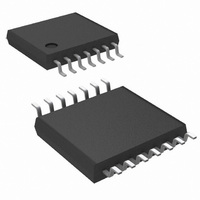
LM2744MTC/NOPB National Semiconductor, LM2744MTC/NOPB Datasheet - Page 9

LM2744MTC/NOPB
Manufacturer Part Number
LM2744MTC/NOPB
Description
IC REG SYNC BUCK N-CH 14-TSSOP
Manufacturer
National Semiconductor
Series
PowerWise®r
Type
Step-Down (Buck)r
Datasheet
1.LM2744MTCXNOPB.pdf
(24 pages)
Specifications of LM2744MTC/NOPB
Internal Switch(s)
No
Synchronous Rectifier
Yes
Number Of Outputs
1
Voltage - Output
0.5 ~ 1.5 V
Current - Output
20A
Frequency - Switching
50kHz ~ 1MHz
Voltage - Input
1 ~ 16 V
Operating Temperature
-40°C ~ 125°C
Mounting Type
Surface Mount
Package / Case
14-TSSOP
For Use With
LM2744EVAL - BOARD EVALUATION LM2744
Lead Free Status / RoHS Status
Lead free / RoHS Compliant
Power - Output
-
Other names
*LM2744MTC
*LM2744MTC/NOPB
LM2744MTC
*LM2744MTC/NOPB
LM2744MTC
Block Diagram
Application Information
THEORY OF OPERATION
The LM2744 is a voltage-mode, high-speed synchronous
buck regulator with a PWM control scheme. It is designed for
use in set-top boxes, thin clients, DSL/Cable modems, and
other applications that require high efficiency buck convert-
ers. It has output shutdown (SD), input undervoltage lock-out
(UVLO) mode and power good (PWGD) flag (based on over-
voltage and undervoltage detection). The overvoltage and
undervoltage signals are OR-gated to drive the power good
signal and provide a logic signal to the system if the output
voltage goes out of regulation. Current limit is achieved by
sensing the voltage V
START UP/SOFT-START
When V
logic high, the soft-start period begins. Then an internal, fixed
10 µA source begins charging the soft-start capacitor. During
soft-start the voltage on the soft-start capacitor C
nected internaly to the non-inverting input of the error ampli-
fier. The soft-start period lasts until the voltage on the soft-
start capacitor exceeds the LM2744 reference voltage. At this
point the reference voltage takes over at the non-inverting er-
ror amplifier input. The capacitance of C
length of the soft-start period, and can be approximated by:
CC
exceeds 2.76V and the shutdown pin (SD) sees a
DS
across the low side MOSFET.
SS
determines the
SS
is con-
9
Where C
During soft-start the Power Good flag is forced low and it is
released when the FB pin voltage reaches 70% of V
this point the chip enters normal operation mode, and the
output overvoltage and undervoltage monitoring starts.
NORMAL OPERATION
While in normal operation mode, the LM2744 regulates the
output voltage by controlling the duty cycle of the high-side
and low-side MOSFETs (see Typical Application Circuit).The
equation governing output voltage is:
The PWM frequency is adjustable between 50 kHz and 1 MHz
and is set by an external resistor, R
pin and ground. The resistance needed for a desired frequen-
cy is approximately:
SS
is in µF and t
C
SS
= t
SS
SS
is in ms.
/ (100 x V
FADJ
REF
, between the FREQ
)
www.national.com
REF
20106003
. At


