MAX829EUK+T Maxim Integrated Products, MAX829EUK+T Datasheet
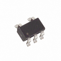
IC INVERTER VOLT SOT23-5

MAX829EUK+T

Manufacturer Part Number
MAX829EUK+T
Description
IC INVERTER VOLT SOT23-5
Manufacturer
Maxim Integrated Products
Type
Switched Capacitor (Charge Pump), Doubler, Invertingr
Datasheet

Specifications of MAX829EUK+T

Internal Switch(s)
Yes
Synchronous Rectifier
No
Number Of Outputs
1
Voltage - Output
-1.15 ~ 6 V, ±2.3 ~ ±12 V
Current - Output
25mA
Frequency - Switching
35kHz
Voltage - Input
1.5 ~ 5.5 V
Operating Temperature
-40°C ~ 85°C
Mounting Type
Surface Mount
Package / Case
SOT-23-5, SC-74A, SOT-25
Function
Inverting
Output Voltage
- 1.5 V to - 5.5 V
Output Current
25 mA
Supply Current
150 uA
Maximum Operating Temperature
+ 85 C
Input Voltage
1.5 V to 5.5 V
Maximum Power Dissipation
571 mW
Minimum Operating Temperature
- 40 C
Mounting Style
SMD/SMT
Switching Frequency
35 KHz
Lead Free Status / RoHS Status
Lead free / RoHS Compliant
Power - Output
-
Lead Free Status / Rohs Status
Lead free / RoHS Compliant
The ultra-small MAX828/MAX829 monolithic, CMOS
charge-pump inverters accept input voltages ranging
from +1.5V to +5.5V. The MAX828 operates at 12kHz,
and the MAX829 operates at 35kHz. Their high efficiency
(greater than 90% over most of the load-current range)
and low operating current (60µA for the MAX828) make
these devices ideal for both battery-powered and board-
level voltage-conversion applications.
The MAX828/MAX829 combine low quiescent current
and high efficiency. Oscillator control circuitry and four
power MOSFET switches are included on-chip.
Applications include generating a -5V supply from a +5V
logic supply to power analog circuitry. Both parts come
in a 5-pin SOT23-5 package and can deliver 25mA with
a voltage drop of 500mV.
For a similar device with logic-controlled shutdown,
refer to the MAX1719/MAX1720/MAX1721. For applica-
tions requiring more power, the MAX860 delivers up to
50mA with a voltage drop of 600mV, in a space-saving
µMAX package.
19-0495; Rev 3; 9/99
For price, delivery, and to place orders, please contact Maxim Distribution at 1-888-629-4642,
or visit Maxim’s website at www.maxim-ic.com.
NEGATIVE VOLTAGE CONVERTER
Small LCD Panels
Cell Phones
Medical Instruments
Handy-Terminals, PDAs
Battery-Operated Equipment
5
3
4
Typical Operating Circuit
________________________________________________________________ Maxim Integrated Products
C1+
C1-
GND
General Description
Switched-Capacitor Voltage Inverters
MAX828
MAX829
OUT
Applications
IN
2
1
INPUT
SUPPLY
VOLTAGE
NEGATIVE
OUTPUT
VOLTAGE
o 5-Pin SOT23-5 Package
o 95% Voltage Conversion Efficiency
o Inverts Input Supply Voltage
o 60µA Quiescent Current (MAX828)
o +1.5V to +5.5V Input Voltage Range
o Requires Only Two Capacitors
o 25mA Output Current
MAX828EUK
MAX829EUK
PART
TOP VIEW
-40°C to +85°C
-40°C to +85°C
TEMP. RANGE
OUT
C1-
IN
1
2
3
Ordering Information
SOT23-5
MAX828
MAX829
Pin Configuration
5 SOT23-5
5 SOT23-5
PACKAGE
5
4
PIN-
C1+
GND
Features
TOP MARK
AABJ
AABI
SOT
1

Related parts for MAX829EUK+T

MAX829EUK+T Summary of contents

Page 1

... MAX829 3 C1- 4 GND NEGATIVE VOLTAGE CONVERTER ________________________________________________________________ Maxim Integrated Products For price, delivery, and to place orders, please contact Maxim Distribution at 1-888-629-4642, or visit Maxim’s website at www.maxim-ic.com. o 5-Pin SOT23-5 Package o 95% Voltage Conversion Efficiency o Inverts Input Supply Voltage o 60µA Quiescent Current (MAX828 ...

Page 2

Switched-Capacitor Voltage Inverters ABSOLUTE MAXIMUM RATINGS IN to GND .................................................................+6.0V, -0.3V OUT to GND .............................................................-6.0V, +0.3V OUT Output Current ...........................................................50mA OUT Short-Circuit to GND ............................................Indefinite Continuous Power Dissipation (T = +70°C) A SOT23-5 (derate 7.1mW/°C above +70°C)...................571mW Stresses beyond those ...

Page 3

Switched-Capacitor Voltage Inverters __________________________________________Typical Operating Characteristics (Circuit of Figure +5V C3 OUTPUT RESISTANCE vs. SUPPLY VOLTAGE MAX829 20 MAX828 1.5 2.5 3.5 4.5 ...

Page 4

Switched-Capacitor Voltage Inverters (Circuit of Figure +5V C3 OUTPUT VOLTAGE vs. OUTPUT CURRENT 0.5 -0 2. 3.3V IN -2.5 -3 -4.5 -5.5 0 ...

Page 5

Switched-Capacitor Voltage Inverters _______________Detailed Description The MAX828/MAX829 capacitive charge pumps invert the voltage applied to their input. For highest performance, use low equivalent series resistance (ESR) capacitors. During the first half-cycle, switches S2 and S4 open, switches S1 and S3 ...

Page 6

Switched-Capacitor Voltage Inverters Flying Capacitor (C1) Increasing the flying capacitor’s size reduces the output resistance. Small C1 values increase the output resis- tance. Above a certain point, increasing C1’s capaci- tance has a negligible effect, because the output resistance becomes ...

Page 7

Switched-Capacitor Voltage Inverters … MAX828 MAX829 “1” … C2 Figure 4. Cascading MAX828s or MAX829s to Increase Output Voltage + MAX828 D1 MAX829 ...

Page 8

... Maxim cannot assume responsibility for use of any circuitry other than circuitry entirely embodied in a Maxim product. No circuit patent licenses are implied. Maxim reserves the right to change the circuitry and specifications without notice at any time. 8 _____________________Maxim Integrated Products, 120 San Gabriel Drive, Sunnyvale, CA 94086 408-737-7600 © 1999 Maxim Integrated Products ...

Related keywords