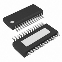
MAX1999EEI+T Maxim Integrated Products, MAX1999EEI+T Datasheet - Page 26

MAX1999EEI+T
Manufacturer Part Number
MAX1999EEI+T
Description
IC CNTRLR PS QUAD HI EFF 28QSOP
Manufacturer
Maxim Integrated Products
Type
Step-Down (Buck)r
Datasheet
1.MAX1977EEIT.pdf
(32 pages)
Specifications of MAX1999EEI+T
Internal Switch(s)
No
Synchronous Rectifier
Yes
Number Of Outputs
4
Voltage - Output
3.3V, 5V, 2 ~ 5.5 V
Current - Output
10A
Frequency - Switching
200kHz, 300kHz, 400kHz, 550kHz
Voltage - Input
6 ~ 24 V
Operating Temperature
-40°C ~ 85°C
Mounting Type
Surface Mount
Package / Case
28-QSOP
Power - Output
860mW
Output Voltage
3.3 V, 2 V to 5.5 V
Input Voltage
6 V to 24 V
Mounting Style
SMD/SMT
Maximum Operating Temperature
+ 85 C
Minimum Operating Temperature
- 40 C
Lead Free Status / RoHS Status
Lead free / RoHS Compliant
High-Efficiency, Quad Output, Main Power-
Supply Controllers for Notebook Computers
When using low-capacity filter capacitors such as
polymer types, capacitor size is usually determined by
the capacity required to prevent V
tripping the undervoltage and overvoltage fault latches
during load transients in ultrasonic mode .
For low input-to-output voltage differentials (V
additional output capacitance is required to maintain sta-
bility and good efficiency in ultrasonic mode.
The amount of overshoot due to stored inductor energy
can be calculated as:
where I
Stability is determined by the value of the ESR zero
(f
of instability is given by the following equation:
where:
For a typical 300kHz application, the ESR zero frequen-
cy must be well below 95kHz, preferably below 50kHz.
Low-ESR capacitors (especially polymer or tantalum),
in widespread use at the time of publication, typically
have ESR zero frequencies lower than of 30kHz. In the
design example used for inductor selection, the ESR
needed to support a specified ripple voltage is found
by the equation:
where LIR is the inductor ripple current ratio and I
is the average DC load. Using a LIR = 0.35 and an
average load current of 5A, the ESR needed to support
50mV
Do not place high-value ceramic capacitors directly
across the fast-feedback inputs (OUT_ to GND for inter-
nal feedback, FB_ divider point for external feedback)
without taking precautions to ensure stability. Large
ceramic capacitors can have a high-ESR zero frequency
and cause erratic, unstable operation. Adding a discrete
resistor or placing the capacitors a couple of inches
downstream from the junction of the inductor and OUT_
may improve stability.
26
ESR
______________________________________________________________________________________
) relative to the switching frequency (f). The point
P-P
PEAK
ripple is 28mΩ.
f
ESR
is the peak inductor current.
V
SOAR
=
ESR
2
×
=
f
ESR
=
π
2
Stability Considerations
LIR
×
V
×
L
≤
RIPPLE P P
×
R
C
π
f
×
ESR
1
I
×
PEAK
I
LOAD
(
V
SAG
×
−
OUT
2
)
C
and V
_
OUT
IN
SOAR
/V
OUT
LOAD
from
<2),
Unstable operation manifests itself in two related but
distinctly different ways: double pulsing and fast-feed-
back loop instability. Noise on the output or insufficient
ESR may cause double pulsing. Insufficient ESR does
not allow the amplitude of the voltage ramp in the output
signal to be large enough. The error comparator mistak-
enly triggers a new cycle immediately after the 350ns
minimum off-time period has expired. Double pulsing
results in increased output ripple, and can indicate the
presence of loop instability caused by insufficient ESR.
Loop instability results in oscillations or ringing at the
output after line or load perturbations, causing the out-
put voltage to fall below the tolerance limit.
The easiest method for checking stability is to apply a
very fast zero-to-max load transient (refer to the
MAX1999 EV kit data sheet) and observe the output
voltage-ripple envelope for overshoot and ringing.
Monitoring the inductor current with an AC current
probe may also provide some insight. Do not allow
more than one cycle of ringing of under- or overshoot
after the initial step response.
The input capacitors must meet the input ripple current
(I
The MAX1777/MAX1977/MAX1999 dual switching regu-
lators operate at different frequencies. This interleaves
the current pulses drawn by the two switches and
reduces the overlap time where they add together. The
input RMS current is much smaller in comparison than
with both SMPSs operating in phase. The input RMS cur-
rent varies with load and the input voltage.
The maximum input capacitor RMS current for a single
SMPS is given by:
when V+ = 2 x V
current of I
The ESR of the input capacitor is important for deter-
mining capacitor power dissipation. All the power
(I
ciency. Nontantalum chemistries (ceramic or OS-CON)
are preferred due to their low ESR and resilience to
power-up surge currents. Choose input capacitors that
exhibit less than +10°C temperature rise at the RMS
input current for optimal circuit longevity. Place the
drains of the high-side switches close to each other to
share common input bypass capacitors.
2 RMS
RMS
) requirement imposed by the switching current.
x ESR) heats up the capacitor and reduces effi-
I
RMS
LOAD
≈
/2.
I
LOAD
OUT_
Input Capacitor Selection
⎛
⎜
⎜
⎜
⎝
(D = 50%), I
V
OUT
_
(
V
V
+ −
+
RMS
V
OUT
has maximum
_
)
⎞
⎟
⎟
⎟
⎠


