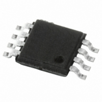
E-L6920DTR STMicroelectronics, E-L6920DTR Datasheet

E-L6920DTR
Specifications of E-L6920DTR
Available stocks
Related parts for E-L6920DTR
E-L6920DTR Summary of contents
Page 1
... The L6920 is a high efficiency step-up controller re- quiring only three external components to realize the conversion from the battery voltage to the selected output voltage. The start up is guaranteed at 1V and the device is op- erating down to 0.6V. Internal synchronous rectifier is implemented with a 120mΩ P-channel MOSFET and, in order to improve the efficiency, a variable frequency control is imple- mented ...
Page 2
... Bypass this output to GND with a 100nF capacitor for filtering high frequency noise. No capacitor is required for stability 5 SHDN Shutdown pin. When pin 5 is below 0.2V the device is in shutdown, when pin 5 is above 0.6V the device is operating. 6 GND Ground pin ...
Page 3
... I LX switch current limit lim T Maximum on time onmax T Minimum off time offmin SHDN SHDN logic LOW SHDN logic HIGH V Reference Voltage ref < 125°C unless otherwise specified) j Test Condition 1.4V 3.3V l out LBI = SHDN = 2V amb 1.4V out LBI = SHDN = 2V, T ...
Page 4
... Figure 4. Efficiency vs. Output Current 100 90 80 Vin = 1. Vout = 47µ 100µ 0.01 0.1 1 LOAD CURRENT [mA] 4/13 Figure 5. Startup Voltage vs Output Current Vin = 2.4V Vin = 1.2V Vout = 3. 47µ 100µF 10 100 1000 Vin = 3.6V Vin = 2.4V 10 100 1000 1.4 1.2 1 0.8 0.6 0.4 0.2 0 ...
Page 5
... This is accomplished by alternating between two basic steps: - TON phase: the energy is transferred from the battery to the inductor by shorting LX node to ground via the N- channel power switch. The switch is turned off if the current flowing in the inductor reaches 1A or after a max- imum on time set to 5µ ...
Page 6
... Trace 4: I out Time div.: 10 µs/div When Iload is heavier, the pulse trains are overlapped. Figures show some possible behaviors. Considering that current in the inductor is limited to 1A, the maximum load current is defined by the following relationship: I load_lim Where η is the efficiency and I lim Of course, if Iload is greater than Iload_lim the regulation is lost (figure 11) ...
Page 7
... Trace 4: I out Time div.: 5 µs/div 4.1 Start-up One of the key features of L6920 is the startup at sup- ply voltage down to 1V (please see the diagram in Figure 5. in case of heavy load). The device leaves the startup mode of operation as soon as VOUT goes over 1.4V. During startup, the synchronous switch is off and the energy is trans- ferred to the load through its intrinsic body diode ...
Page 8
... Jumper J1 J2 R4, R5 should be selected in the range of 100kΩ - 10MΩ to minimize consumption and error due to current sunk by FB pin (few nA). 5.2 Output capacitor selection The output capacitor affects both efficiency and output ripple so its choice has to be considered with particular care. The capacitance value should be in the range of about 10µ ...
Page 9
... It is essential to keep as small as possible the high switching current circulating paths to reduce radiation and resonance problems. So, the output and input cap should be very close to the device. The external resistor dividers, if used, should be as close as possible to the pins of the device (FB and LBI) and as far as possible from the high current circulating paths, to avoid pick up noise. ...
Page 10
... L6920 Figure 13. Demoboard Components (Top side). Figure 14. Demoboard Layout (Top side). Figure 15. Demoboard Layout (Bottom side). 10/13 4.5cm 4cm 4.5cm 4cm 4.5cm 4cm ...
Page 11
... L 0.450 0.600 0.750 L1 1.000 k 0˚ (min.) 8˚ (max.) aaa 0.100 Note and F does not include mold flash or protrusions. Mold flash or potrusions shall not exceed 0.15mm (.006inch) per side. inch MIN. TYP. MAX. 0.047 0.002 0.006 0.031 0.039 0.041 ...
Page 12
... L6920 7 Revision History Table 9. Revision History Date Revision May 2003 February 2005 12/13 1 First Issue. 2 Modified the max. value of the I Description of Changes parameter in the Table 4 pag ...
Page 13
... STMicroelectronics. The ST logo is a registered trademark of STMicroelectronics. Australia - Belgium - Brazil - Canada - China - Czech Republic - Finland - France - Germany - Hong Kong - India - Israel - Italy - Japan - Malaysia - Malta - Morocco - Singapore - Spain - Sweden - Switzerland - United Kingdom - United States of America All other names are the property of their respective owners © ...


