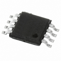
E-L6920DTR STMicroelectronics, E-L6920DTR Datasheet - Page 6

E-L6920DTR
Manufacturer Part Number
E-L6920DTR
Description
IC BOOST SYNC FIX/ADJ 8TSSOP
Manufacturer
STMicroelectronics
Type
Step-Up (Boost)r
Datasheet
1.L6920DC.pdf
(13 pages)
Specifications of E-L6920DTR
Internal Switch(s)
Yes
Synchronous Rectifier
Yes
Number Of Outputs
1
Voltage - Output
3.3V, 5V, Adj
Voltage - Input
0.6 ~ 5.5 V
Operating Temperature
-40°C ~ 85°C
Mounting Type
Surface Mount
Package / Case
8-TSSOP
Output Voltage
5.2 V
Mounting Style
SMD/SMT
Lead Free Status / RoHS Status
Lead free / RoHS Compliant
Current - Output
-
Power - Output
-
Frequency - Switching
-
Lead Free Status / Rohs Status
Lead free / RoHS Compliant
Other names
497-4593-2
Available stocks
Company
Part Number
Manufacturer
Quantity
Price
L6920
Figure 7. PFM mode Condition: V
Trace1: Vout (50mV~/div) Trace 4: IL (100mA/div)
Time div.: 5µs/div
Figure 8. Heavier load - Train pulses overlapping.
Trace1: V
Time div.: 10 µs/div
When Iload is heavier, the pulse trains are overlapped. Figures 7 - 8 show some possible behaviors.
Considering that current in the inductor is limited to 1A, the maximum load current is defined by the following
relationship:
Where η is the efficiency and I
Of course, if Iload is greater than Iload_lim the regulation is lost (figure 11).
6/13
out
(100mV~/div) Trace 4: I
I
load_lim
lim
=1A.
out
=
L
= 5V; V
(200mA/div)
---------- -
V
V
out
in
in
⋅
⎛
⎝
=1.5V.
I
lim
–
T
off min
Figure 9. Heavy load - Inductor current ripples
below I
(200mA/div) Time div.: 20 µs/div
Figure 10. Heavy load and High ESR. Regulation
falls in continuous mode of operation. Trace1:
V
div.: 5 µs/div
out
⋅
V
------------------------- -
(100mV~/div) Trace 4: I
out
2 L
lim
⋅
–
Trace1: V
V
in
⎞ η
⎠
⋅
eq. (1)
out
(100mV~/div) Trace 4: I
L
(200mA/div). Time
L


