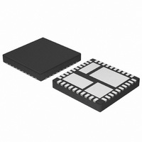
NCP3101BMNTXG ON Semiconductor, NCP3101BMNTXG Datasheet - Page 22

NCP3101BMNTXG
Manufacturer Part Number
NCP3101BMNTXG
Description
IC CONV VOLT SYNC BUCK 6A 40-QFN
Manufacturer
ON Semiconductor
Type
Step-Down (Buck)r
Datasheet
1.NCP3101BMNTXG.pdf
(26 pages)
Specifications of NCP3101BMNTXG
Internal Switch(s)
Yes
Synchronous Rectifier
Yes
Number Of Outputs
1
Voltage - Output
Adj to 0.8V
Current - Output
6A
Frequency - Switching
275kHz
Voltage - Input
4.5 ~ 13.2 V
Operating Temperature
-40°C ~ 85°C
Mounting Type
Surface Mount
Package / Case
40-TQFN Exposed Pad
Power - Output
3W
Lead Free Status / RoHS Status
Lead free / RoHS Compliant
current during max load, then an input fuse should be rated
accordingly using I
If the inrush current is higher than the steady state input
Figure 35. Voltage Enable Load Current
Voltage
Output
Current
Output
2
t methodology.
1.0V
tss
t
3.3V
http://onsemi.com
22
Layout Considerations
layout is very important. Using a good layout can solve
many problems associated with these types of power
supplies as transients occur.
for converter stability. They should be placed close to the
NCP3101C. The feedback trace is recommended to be kept
as far from the inductor and noisy power traces as possible.
The resistor divider and feedback acceleration circuit (R2,
R3, R6, C13) are recommended to be placed near output
feedback (Pin 16, NCP3101C).
generate voltage transients across the impedances of the
interconnecting bond wires and circuit traces. The
interconnecting impedances should be minimized by using
wide, short printed circuit traces. The critical components
should be located together as close as possible using ground
plane construction or single point grounding. The inductor
and output capacitors should be located together as close as
possible to the NCP3101C.
When designing a high frequency switching converter,
External compensation components (R1, C9) are needed
Switching current from one power device to another can


