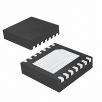
MAX4921BETD+T Maxim Integrated Products, MAX4921BETD+T Datasheet

MAX4921BETD+T
Specifications of MAX4921BETD+T
Related parts for MAX4921BETD+T
MAX4921BETD+T Summary of contents
Page 1
... PIN- PART PACKAGE MAX4919BETD+T 14 TDFN-EP* MAX4920BETD+T 14 TDFN-EP* MAX4921BETD+T 14 TDFN-EP* Note: All devices are specified over the -40°C to +85°C operating temperature range. +Denotes lead-free package. *EP = Exposed paddle. ________________________________________________________________ Maxim Integrated Products For pricing, delivery, and ordering information, please contact Maxim/Dallas Direct! at 1-888-629-4642, or visit Maxim’ ...
Page 2
Battery Power-Up Logic with Overvoltage and Overcurrent Protection ABSOLUTE MAXIMUM RATINGS IN to GND ...............................................................-0.3V to +30V GP1, GN1 to GND ..................................................-0.3V to +12V IN to GP1 ................................................................-0.3V to +20V BTO to GND ..........................................................-0.3V to +6.1V BTI to BTO ................................................................-0.3V ...
Page 3
Battery Power-Up Logic with Overvoltage ELECTRICAL CHARACTERISTICS (continued (MAX4919B/MAX4920B are +25°C.) (Note 1) A PARAMETER SYMBOL GATE DRIVERS GN1 Turn-On Voltage GN1 Pulldown Current GP1 Clamp Voltage V GP1 Pulldown Resistor ...
Page 4
Battery Power-Up Logic with Overvoltage and Overcurrent Protection ELECTRICAL CHARACTERISTICS (continued (MAX4919B/MAX4920B are +25°C.) (Note 1) A PARAMETER SYMBOL GN1 Turn-Off Time t GOFF Initial Overvoltage Fault Delay t OVLO ...
Page 5
Battery Power-Up Logic with Overvoltage ( +25°C, unless otherwise noted.) BTI A CURRENT LIMIT vs. TEMPERATURE 4.0 3.8 3.6 3.4 3.2 3.0 2.8 2.6 2.4 2.2 2.0 -40 -15 10 TEMPERATURE (°C) NORMALIZED UVLO THRESHOLD vs. ...
Page 6
Battery Power-Up Logic with Overvoltage and Overcurrent Protection ( +25°C, unless otherwise noted.) BTI A UNDERVOLTAGE RESPONSE 1µs/div BATTERY-SWITCH TURN-OFF RESPONSE (PWR_ON FALLING BTI 1ms/div SHORT-CIRCUIT RESPONSE 2ms/div 6 _______________________________________________________________________________________ Typical Operating Characteristics ...
Page 7
Battery Power-Up Logic with Overvoltage PIN NAME p-Channel MOSFET Gate-Drive Output. GP1 pulls the external pFET gate down when the input is above 1 GP1 ground. Voltage Input. IN powers the charge pump required to turn on GN1. When the ...
Page 8
Battery Power-Up Logic with Overvoltage and Overcurrent Protection ADAPTER VOLTAGE IN ACOK ACOK ONE-SHOT P2 STATUS Figure 1. ACOK One-Shot Timing Diagram An internal 5.5V supply powers the on-chip charge pump used to drive GN1 above IN, allowing the use ...
Page 9
Battery Power-Up Logic with Overvoltage HP_PWR t HPDBC t 1SHHP HP_PWR ONE-SHOT OFF P2 ON STATUS Figure 2. HP_PWR One-Shot Timing Diagram ACOK ONOK PWR_ON PWR_HOLD Figure 4. Functional Diagram _______________________________________________________________________________________ and Overcurrent Protection IN GP1 OFF ACOK Figure 3. ...
Page 10
Battery Power-Up Logic with Overvoltage and Overcurrent Protection PWR_HOLD controls the turn-on of the 1.8A (min) cur- rent-limit switch (P2). When a voltage is present at IN, for 25ms, ACOK pulls low and V < V < V UVLO IN ...
Page 11
Battery Power-Up Logic with Overvoltage ADAPTER VOLTAGE IN ACOK ACOK ONE-SHOT PWR_HOLD STATUS P2 Figure 7. MAX4919B/MAX4920B/MAX4921B Power_Hold Waveform When Voltage Present Note that upon V falling below the 2.15V (min) thresh- BTI old, the internal switch ...
Page 12
Battery Power-Up Logic with Overvoltage and Overcurrent Protection Table 1. MOSFET Suggestions CONFIGURATION/ PART PACKAGE Complementary Si5504DC MOSFET/1206-8 Si5902DC Dual/1206-8 Si1426DH Single/µDFN-6 Si5435DC Single/1206-8 FDC6561AN Dual/SSOT-6 FDG315N Single/µDFN-6 FDC658P Single/SSOT-6 FDC654P Single/SSOT-6 MOSFET Selection The MAX4919B/MAX4920B/MAX4921B are designed for use ...
Page 13
Battery Power-Up Logic with Overvoltage HP_PWR t HPDBC t 1SHHP HP_PWR ONE-SHOT OFF P2 STATUS ON PWR_HOLD Figure 8. MAX4919B/MAX4920B/MAX4921B Power_Hold Waveform When Voltage IN is Not Present Additional Applications Information Figures 11 and 12 depict the MAX4919B/MAX4920B being utilized ...
Page 14
Battery Power-Up Logic with Overvoltage and Overcurrent Protection MAX4919B MAX4920B MAX4921B BTI BTO Figure 9. MAX4919B/MAX4920B/MAX4921B Current-Limit Diagram 14 ______________________________________________________________________________________ TURN-ON PHASE V BTO I LIM CLIM V ONOK PROCESS: BiCMOS SHORT CIRCUIT t ...
Page 15
Battery Power-Up Logic with Overvoltage AC ADAPTER µP Figure 10. Back-to-Back External MOSFET Configuration AC ADAPTER µP Figure 11. MAX4919B/MAX4920B Always Powered From Battery (Car-Kit Adapter Never Plugged In) ______________________________________________________________________________________ and Overcurrent Protection 1µ GP1 IN MAX4919B MAX4920B ...
Page 16
Battery Power-Up Logic with Overvoltage and Overcurrent Protection IN ACOK ACOK ONE-SHOT PWR_HOLD P2 STATUS PWR_ON ONOK Figure 12. MAX4919B/MAX4920B Timing Diagram For Non-Car-Kit Adapter Application 16 ______________________________________________________________________________________ 25ms DEBOUNCE PERIOD 1.2s ONE-SHOT PERIOD OFF ON OVLO UVLO OFF ON ...
Page 17
Battery Power-Up Logic with Overvoltage V IO µP V BAT Figure 13. MAX4920B With Car-Kit Adapter and Built-In Charger Connected HP_PWR 25ms DEBOUNCE PERIOD HP_PWR ONE-SHOT PWR_HOLD PWR_ON ONOK P2 STATUS Figure 14. Timing Diagram For Car-Kit Adapter Application ______________________________________________________________________________________ ...
Page 18
Battery Power-Up Logic with Overvoltage and Overcurrent Protection ADAPTER AND CHARGER CIRCUITRY V IO µP V BAT AC ADAPTER V IO µP V BAT 18 ______________________________________________________________________________________ N 1µF GP1 IN GN1 ACOK MAX4921B ONOK PWR_HOLD PWR_ON GND EN HP_PWR OPTIONAL ...
Page 19
... Maxim cannot assume responsibility for use of any circuitry other than circuitry entirely embodied in a Maxim product. No circuit patent licenses are implied. Maxim reserves the right to change the circuitry and specifications without notice at any time. Maxim Integrated Products, 120 San Gabriel Drive, Sunnyvale, CA 94086 408-737-7600 ____________________ 19 © 2006 Maxim Integrated Products and Overcurrent Protection PACKAGE OUTLINE, 6,8,10 & ...


