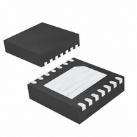
MAX4921BETD+T Maxim Integrated Products, MAX4921BETD+T Datasheet - Page 10

MAX4921BETD+T
Manufacturer Part Number
MAX4921BETD+T
Description
IC CTLR OVP/OCP BATT PWR 14-TDFN
Manufacturer
Maxim Integrated Products
Datasheet
1.MAX4921BETDT.pdf
(19 pages)
Specifications of MAX4921BETD+T
Applications
*
Mounting Type
Surface Mount
Package / Case
14-TDFN Exposed Pad
Lead Free Status / RoHS Status
Lead free / RoHS Compliant
PWR_HOLD controls the turn-on of the 1.8A (min) cur-
rent-limit switch (P2). When a voltage is present at IN,
and V
and issues an internal one-shot pulse that turns on P2
temporarily for 1.2s (typ). During the 1.2s one-shot peri-
od, the MAX4919B/MAX4920B/MAX4921B must see a
low-to-high transition at PWR_HOLD (and PWR_HOLD
must remain high), for P2 to remain on (see Figure 7).
P2 turns off when PWR_HOLD and PWR_ON are low,
and when the HP_PWR and ACOK internal one-shot
timers have expired.
When a voltage at IN is not present, HP_PWR controls
the turn-on of P2. Upon a low-to-high transition at
HP_PWR (and HP_PWR remaining high), the
MAX4919B/MAX4920B/MAX4921B issue an internal
HP_PWR one-shot signal that turns on P2 temporarily
for 1.2s (typ). During the 1.2s one-shot period, the
MAX4919B/MAX4920B/MAX4921B must see a low-to-
high transition at PWR_HOLD (and PWR_HOLD must
remain high) for P2 to remain on. P2 turns off when
PWR_HOLD and PWR_ON are low, and when the
HP_PWR and ACOK internal one-shot timers have
expired (see Figure 8).
The MAX4919B/MAX4920B/MAX4921B feature an inter-
nal 1.8A (min) current-limiting switch (P2) at BTO. The
current limit remains in effect throughout BTI’s input
supply-voltage range.
The current limit takes care of two situations: when P2 is
initially turned on, and when P2 is already on and a
short circuit occurs (see Figure 9). When P2 is turned
on, the current can be high because BTO = 0 and a
large load capacitor needs to be charged. The protec-
tion circuit prevents the load current from exceeding
the 1.8A (min) current-limit value, and BTO will have a
smooth turn-on (the larger the capacitor, the slower the
turn-on). The 10ms blanking time avoids a false fault
assertion. At the end of the blanking time, if the device
is still limiting, a fault is asserted and P2 immediately
turns off. When the switch is already on and a short-cir-
cuit condition occurs at BTO, the device limits the cur-
rent. If the fault condition duration is greater than the
blanking time, P2 turns off.
Before P2 turns on again, any condition that is attempt-
ing to turn it on must be first removed, i.e. the one-shot
(from IN or HP_PWR) must be completed, and PWR_ON
and PWR_HOLD must be low. If the three conditions are
satisfied, P2 turns on again only if either IN or
PWR_HOLD is cycled OFF and ON.
Battery Power-Up Logic with Overvoltage
and Overcurrent Protection
10
______________________________________________________________________________________
UVLO
< V
IN
< V
OVLO
for 25ms, ACOK pulls low
Current Limiting
PWR_HOLD
The MAX4919B/MAX4920B/MAX4921B operate in low-
battery mode when the battery voltage at BTI is greater
than 2.15V but less than 2.8V (typ). In low-battery opera-
tion, PWR_ON does not influence the behavior of the
internal switch.
When an adapter and car kit are not present, the internal
switch is typically controlled by PWR_HOLD. If PWR_ON
is high (ONOK is low) and BTI falls below 2.8V, ONOK
pulls high, but the internal switch remains on since
PWR_HOLD is high. If PWR_ON is high and PWR_HOLD
is low when V
nal switch turns off immediately. Upon BTI rising above
2.8V again, PWR_ON is again enabled and ONOK goes
back to its previous logic level before a low condition at
BTI occurred.
Figure 5. ONOK Timing Diagram
Figure 6. BTI Falling and Rising Above Its Thresholds
PWR_ON
ONOK
PWR_ON
BT1
ONOK
P2
ON
BTI
V
falls below the 2.8V threshold, the inter-
LVBTI
OFF
Low-Battery Operation
V
UVBTI
ON
OFF


