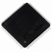
STV0674T100 STMicroelectronics, STV0674T100 Datasheet - Page 23

STV0674T100
Manufacturer Part Number
STV0674T100
Description
IC PROCSR CAM CMOS DGITL 100TQFP
Manufacturer
STMicroelectronics
Datasheet
1.STV0674T100.pdf
(35 pages)
Specifications of STV0674T100
Applications
*
Mounting Type
Surface Mount
Package / Case
100-TQFP, 100-VQFP
Lead Free Status / RoHS Status
Lead free / RoHS Compliant
Available stocks
Company
Part Number
Manufacturer
Quantity
Price
Company:
Part Number:
STV0674T100
Manufacturer:
SILICON
Quantity:
5
Company:
Part Number:
STV0674T100
Manufacturer:
STMicroelectronics
Quantity:
10 000
STV0674
4.9
Note:
Device current consumption in run and suspend modes
The STV0674 power consumption has been estimated based on a webcam configuration. In this
way, the analysis can specifically consider the device’s intrinsic power consumption rather than that
associated with other system-level components. As STV0674 typically ends up in very low USB or
battery powered applications, it is important device power consumption is measured in three
different operating modes representing typical operating conditions in the real application.
These three modes shall be referred to as low power mode, high power mode and suspend mode.
Suspend mode is the is the lowest power mode of the device. For the core current, it can be
effectively equated to ‘static’ power consumption. In this mode, all embedded clocks are stopped
and all embedded logic blocks, macros, IP, etc. are reset into their low power modes. The XTAL
oscillator pads (providing main clock source to entire STV0674) are also stopped. The name
‘Suspend’ mode historically comes from the device’s requirement to comply with USB ‘suspend’
mode where the total current drawn from the host PC by the USB peripheral is not allowed to
exceed 500 µA.
In low power mode, the embedded VP and VC module clocks are disabled and held in reset. The
VP and VC are the two most power-hungry modules in the STV0674. A limited number of modules
are enabled in this mode to allow USB enumeration, system-level self-configuration or camera user-
interface functions. Such modules include the embedded microcontroller, USB core, memory sub-
systems and SFP core.
In high power mode. The VP and VC module clocks is enabled and are brought out of reset. This is
more typical of the real device application in that video data is being generated and processed. In
measured cases the VP and VC are set up to their fastest (worst-case power) modes of operation
processing VGA source data from the sensor at full 30 frames-per-second.
The baseline device power model presented here can be extended to cover other system-level
configurations. In such cases the core I
is more likely to vary depending for example on which memory type (sdram/nand) is being used.
The power associated with each pin can be calculated based on its frequency (MHz), capacitive (C)
and resistive (R) loading.
DD
will remain as measured here (30fps/VGA) but the i/o I
Detailed Specifications
23/35
DD


